Instrument Safety Factor
Instrument Safety Factor (ISF) is defined as the ratio of CT saturation current to its rated current. Suppose the CT ratio is 2000/1 and the CT gets saturated if there is flow of 10 kA current through its primary, then Instrument Safety Factor is given as
ISF is defined only for metering current transformer (CT). Metering CT is nothing but a CT used for metering purpose.
Need of Instrument Safety Factor
Generally a CT have more than one core say 4 cores. Different cores are designed for different purpose like Core-1, Core-2 and Core-4 are meant for protection purpose whereas Core-3 is meant for metering as shown in figure below.
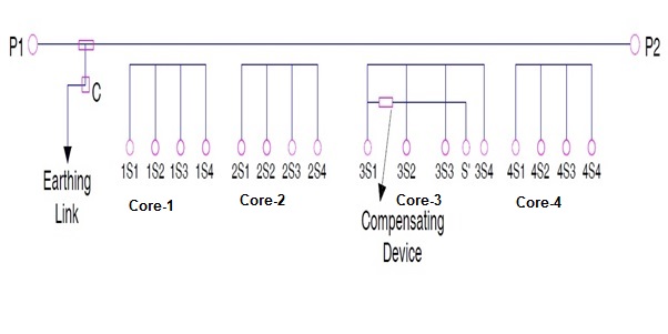
Thus ISF will be defined for metering core i.e. core-3 of CT. Since meters are only designed for low value of current, therefore it is very important to protect them from high value of current. As meters are connected directly with the terminals of metering core of CT, it may happen so that during fault condition the secondary current of CT may be high which in turn will flow through the connected meter. This may lead to the damage of meter coil. Therefore some measure must be taken to protect meters from such event. This is the reason we define Instrument Safety Factor, ISF for metering CT. Now the question arises, how does defining ISF protects connected meters from over current?
Well, suppose there occurs some fault in the system. Assume that the fault current is 6 times the rated primary current of CT i.e. 6×2000 A. In this case, if the ISF value of CT is 5 then it is most likely to saturate and hence the secondary current of CT metering core will become zero. Thus there will not any flow of current through the connected meters during such fault. In this way, meters are protected from over current during fault. You may think of overload condition like everything is normal but the load current is say 4000 A. In this case CT secondary current will be 2 A which will flow through the meter but it should be noted that meters are designed for certain overloading. Based on meter overloading, Instrument Safety Factor of CT is chosen. Thus meters always remain protected.
|
Why secondary current of CT becomes zero during saturation? Since during CT saturation, the magnetic flux in the core will become almost constant, this means that there will be no change in the flux and hence no induced emf. As there is no induced emf, hence there will not be any transformer action. This means that there will not be any CT secondary current. |
If you see the name plate of metering core of a Current Transformer (CT), you will notice ISF value mentioned.
Compensating Device – Purpose
A compensating device is generally used in metering CT as shown in figure above. The basic purpose of this compensating device is to achieve the Instrument Safety Factor. This device is nothing but high resistance.
Isf calculate
Does ISF applicable for low ratio wound primary CT
How CBCT is designed?
The picture of CT is not visible.