Current Transformer is an instrument transformer which steps down high value of current to a low value of current suitable for measurement devices. It is widely used in power system for measurement and protection purpose. We cannot think of power generation, transmission or distribution without using Current Transformer.
Construction of Current Transformer (CT):
There are two windings in a Current Transformer which are wound around a magnetic core. The winding having fewer numbers of turns is called Primary Winding and the winding having more turns is called Secondary winding. Primary winding is connected in series with the primary circuit i.e. the circuit in which current is to be measured. As the number of turns in primary winding is very less, therefore there is no any appreciable amount of voltage drop in this winding.
The secondary winding is connected with ammeter / wattmeter / protection relay coil. Since the impedance of metering / protection relay is very less, therefore we can say that a CT operates under short circuit condition.
Based on the construction, there are two types of current transformer. One is Live Tank CT and another one is Dead Tank CT. In both types, the core and windings are enclosed in a porcelain structure. This structure is filled with oil which provides necessary cooling to core as well as winding. Kraft paper provides insulation between core and winding. In the figure below, the three equipment in the front are live tank CT.
Symbol of Current Transformer:
A current transformer is shown as below.
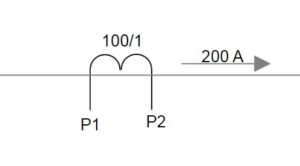
In the above figure, CT is defined by its terminal P1 & P2 and ratio 100/1. Primary circuit in which CT is connected is shown carrying a current of 200 A. The secondary current of CT will be 200 / 100 = 2 A.
Parameters of Current Transformer:
A current transformer is defined by its current Turn Ratio, Accuracy Class, Accuracy Limit Factor and Instrument Safety Factor (ISF) etc. Accuracy class is determined by phase angle error and ratio error. In this post we will be discussing the basics. Before going into further discussion, it is better to understand some of the basic but important parameters. Ther are as follows:
- Turn Ratio is defined as the ratio of number of secondary winding turns to number of primary winding turns. It is often denoted by n and given as
n = Number of secondary winding turns / Number of primary winding turns
- Transformation Ratio is defined as the ratio of primary winding current to secondary winding current. It is denoted by R and given as
R = primary winding current / Secondary winding current
You might think that n & R should be equal. Yes, correct but this is the ideal case but there is nothing ideal. There are always some losses associated in a CT and hence Turn Ratio and Transformation Ratio are not equal.This gave rise to ratio error. We will discuss it latter in this post.
- Burden is defined as the volt ampere (VA) of connected load across the terminals for secondary winding of CT.
Equivalent Circuit of Current Transformer:
The equivalent circuit and phasor diagram of current transformer is shown in figure below.
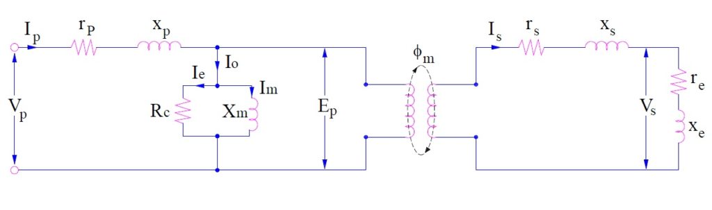
Where
n = turn ratio
rs = resistance of secondary winding
xs = reactance of secondary winding
re = resistance of burden connected to secondary
xe = reactance if burden connected to secondary
Ep = Induced emf in CT primary
Es = Induced voltage in CT secondary
Np = CT primary winding turns
Ns = CT secondary winding turns
Ip = CT primary winding current
Is = CT secondary winding current
Ø = Flux in CT core
ɵ = Phase angle of CT
I0 = Excitation current of CT
Im = Magnetizing current of CT
Phasor Diagram of Current Transformer:
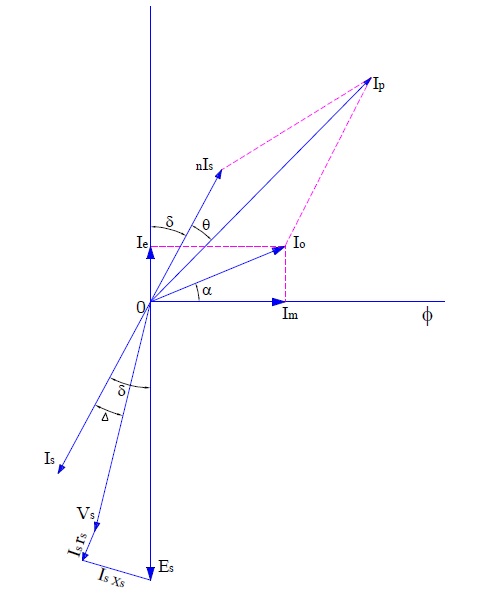
Carefully observe that the equivalent circuit and phasor diagram are same as that of power transformer. The phasor diagram is drawn assuming that connected burden is of lagging power factor. As CT is connected in series with the primary circuit whose current is to be measured, this means that primary current Ip of CT is not dependent on secondary burden rather it is determined by the primary circuit current.
From the above phasor, we will calculate the Transformation Ratio and Phase angle of CT.
Transformation Ratio:
For finding transformation ratio we need to calculate primary current Ip as per definition and then divide it by secondary current Is. Let us consider the part of phasor of our importance for calculating Ip as shown below.
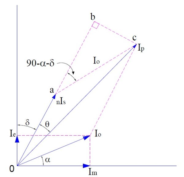
From the above phasor, it can be easily observed that primary current Ip is phasor sum of nIs and I0. The angle between and is (90-α-δ). (How?)
This is because I0 and ac are parallel line and a third line oa is cutting this parallel line. Hence corresponding angles will be equal.
Therefore primary current Ip can be calculated using vector addition formula.
Ip = [(nIs)2+(I0)2+2nIsI0Cos(90-α-δ)]1/2
= [(nIs)2+(I0)2+2nIsI0Sin(α+δ)]1/2
Hence,
Transformation Ratio,
R = Ip/Is
= [(nIs)2+(I0)2+2nIsI0Sin(α+δ)]1/2 / Is
Since magnetizing current I0 is very very small when compared with primary current Ip, therefore for approximation we can proceed as below,
R = [(nIs)2+(I0)2+2nIsI0Sin(α+δ)]1/2 / Is
= [(nIs)2+(I0 Sin(α+δ))2+2nIsI0Sin(α+δ)]1/2 / Is
= [{nIs+ I0 Sin(α+δ)}2]1/2 / Is
= [nIs+ I0 Sin(α+δ)] / Is
= n + (I0/ Is)Sin(α+δ)
Thus.
|
Transformation Ratio R = n + (I0/ Is)Sin(α+δ) |
Following points should be noted from the above expression:
- Transformation ratio is not equal to CT turn ratio.
- Transformation ratio depends on excitation current and excitation angle.
- For transformation ratio to be equal to turn ratio, α = δ =0. This means that there should not be any core loss in the current transformer and burden should be purely resistive.
Phase Angle of Current Transformer:
Phase angle of current transformer is the angle between the primary current Ip and secondary current Is when reversed. In above phasor diagram, θ is the phase angle.

In the above phasor, consider right angled triangle obc
tanθ = bc/ob
= I0Sin(90-α-δ) / (oa+ab)
= I0Cos(α+δ) / [nIs+I0Sin(α+δ)]
Since θ is very small, hence tanθ will be approximately equal to θ. Therefore we can write,
Θ = I0Cos(α+δ) / [nIs+I0Sin(α+δ)]
Also, I0 is very very small, therefore I0Sin(α+δ)<<<<nIs, neglecting I0Sin(α+δ)
Θ = I0Cos(α+δ) / nIs
= [I0CosαCosδ – I0SinαSinδ] / nIs
From phasor, Im = I0Cosα and Ie = I0Sinα, hence
Θ = [ImCosδ – IeSinδ] / nIs Radian
= (180/π) [ImCosδ – IeSinδ] / nIs degree
|
Phase Angle Θ = (180/π) [ImCosδ – IeSinδ] / nIs degree |
Ratio Error of Current Transformer:
Ratio Error is defined as the per unit deviation in transformation ratio from nominal ratio. It is expressed in percentage.
Percentage Ratio Error E
= (Nominal Ration – Transformation Ratio)x100 / Transformation Ratio
Since the burden of current transformer is usually resistive, therefore power factor of burden is almost unity. Hence δ=0,
R = n + (I0Sinα / Is) but I0Sinα = Ie
= n + Ie/Is
Therefore, percentage ratio error can be calculated easily.
Phase Angle Error of Current Transformer:
Ideally the angle between the primary current and secondary current should be 180 degree. But there is some deviation from 180 degree. This deviation is called phase angle error. As can be seen from phasor, this departure is by an angle θ. This means,
Phase difference between primary current and secondary current = θ
Since the burden of current transformer is usually resistive, therefore power factor of burden is almost unity. Hence δ=0. Therefore
Phase angle error θ = (180/π) Im / nIs degree
Precaution:
CT secondary should never be kept open. An open CT secondary causes a high voltage across the CT secondary terminals which may cause damage of equipment / personnel.
Sir kindly give a practical example of ratio error calculation
You want ratio error calculation. I will post on it soon.
Nice representation of the phasor and good explanation
Thank you!
I want an explanation on ratio error and phase angle error of a CT
A carrent transformer has a phase error 3 degree. The phase angal between the primary and secondary carrent is….?…
Sir please given this ans…?
Please advise me that:-
What is effect in durability of PT, Accuracy of PT, Power loss, if phase angle error found in out of limit