ABCD parameters are generalized parameters of transmission line. These parameters are quite helpful for calculation and analysis of transmission line. In any four terminal network, the input voltage and current can be expressed in terms of output voltage and current provided the network should be passive, linear and bilateral. Fortunately, a transmission line is a four terminal network and above all it is a passive, linear and bilateral network. Therefore, input voltage and current of transmission line can be expressed in terms of output voltage and current.
For a transmission line, it is better to call input voltage and current as Sending end voltage and current. Similarly, output voltage as receiving end voltage and current.
Let
VR = Receiving end voltage
Vs = Sending end voltage
Is = Sending end current
IR = Receiving end current
Thus we can write,
Vs = AVR + BIR …………………..(1)
Is = CVR + DIR ……………………(2)
Here A, B, C and D are constants and known as Generalized Circuit Constants of transmission line. The values of constants can easily be calculated from the above equations. For calculating the values of the ABCD parameters, we will consider two cases. Bold sign in the entire post means vector form of the quantity.
Case (1): When Receiving end is open.
As the receiving end is open, therefore load current through the line will be zero. Thus IR = 0.
From equation (1).
A = Vs / VR
Notice that the unit of A is unitless and hence called voltage ratio.
From equation (2),
C = Is / VR
From the above expression of constant C, it is clear that, the unit of C is Mho. This constant is known as open circuit conductance.
Case (2): When receiving end is shorted.
As the receiving end is shorted, therefore load end voltage will be zero. Thus VR = 0.
From equation (1),
B = Vs / IR
Notice that the unit of B is same as that of impedance i.e. Ohm and called short circuit resistance.
From equation (2),
D = Is / IR
Thus D is a dimension less quantity and known as current ratio.
| Generalized Circuit Parameters | Value | Unit |
| Voltage Ratio, A | Vs/VR | Unit less |
| Short Circuit Resistance, B | Vs / IR | Ohm |
| Open Circuit Conductance, C | Is / VR | Mho |
| Current Ratio, D | Is / VR | Unit less |
Features of ABCD Parameters
Following are some of the important points about ABCD parameters, which shall always be kept in mind:
- The constants A, B, C and D are usually complex numbers and hence a phasor.
- For a given system,
A = D
and AD – BC = 1
Determination of ABCD Parameters for Transmission Line
We will determine the value of these parameters for Short as well as Medium Transmission lines.
Short Transmission Line – ABCD Parameters
As we know that, the effect of shunt capacitance in short transmission line is neglected, therefore the equivalent circuit for single phase for short transmission line can be shown as below.

From the figure above,
Is = IR ………………………(3)
and Vs = VR + IRZ …………..(4)
Comparing equation (3) & (4) with equation (1) & (2), we get
A = 1, B = Z, C = 0 and D = 1
Thus we see that, A = D and AD – BC = 1
Medium Transmission Line – ABCD Parameters
We will find the ABCD parameters for two models of medium transmission line i.e. for Nominal T Model and Nominal π Model.
Nominal T Model
The equivalent circuit diagram for Nominal T model for single phase of transmission line is shown in figure below.
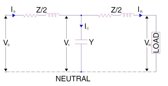
From the figure above,
Vs = V1 + IsZ/2 (These are in phasor from)
But V1 = VR + IRZ/2 (These are in phasor from)
Again,
Ic = Is – IR
= V1Y where Y = Shunt admittance
= Y (VR + IRZ/2 )
Therefore,
Is = IR + YVR + YIRZ/2
= YVR + IR(1 + YZ / 2) ……………………….(5)
Putting the value of V1 in the expression of Vs, we get
Vs = VR + IRZ/2 + IsZ/2
Putting the value of Is in the above expression, we get
Vs = (1 + YZ / 2)VR + (Z + YZ2 / 4) IR ……………(6)
Comparing equation (6) with (1), we get
A = 1 + YZ / 2
B = Z + YZ2 / 4 = Z(1 + YZ / 4)
Comparing equation (5) with (2), we get
C = Y
D = 1 + YZ / 2
Thus the ABCD Parameters for Nominal T model of medium transmission line are
A = D = 1 + YZ / 2
B = Z(1 + YZ / 4)
C = Y
Nominal π Model
The equivalent circuit diagram for Nominal π model for single phase of transmission line is shown in figure below.

As clear from the figure above,
Is = IL + IC2
Is = IL + VsY/2 where Y = Shunt Admittance = jωC
Again,
IL = IR + IC1
= IR + VRY/2 where Y = Shunt Admittance = jωC
Now, we will calculate the value of sending end voltage and current in terms of receiving end voltage and current.
Vs = VR + ILZ
Putting the value of IL, we get
Vs = VR + (IR + VRY/2) Z
Vs = VR + (IR + VRY/2) Z
= (1 + YZ/2) VR + (Z) IR ………………………………(7)
Now,
Is = IL + VsY/2
Putting the value of IL we get,
Is = (IR + VRY/2) + VsY/2
Now, putting the value of Vs we get,
Is = (IR + VRY/2) + [(1 + YZ/2) VR + (YZ / 2) IR ]xY/2
= (1+ YZ/2)IR + Y (1+ YZ/4)VR ………………………………(8)
Comparing equation (7) with (1),
A = 1 + YZ/2
B = Z
Comparing equation (8) with (2),
C = Y (1+ YZ/4)
D = 1 + YZ/2
Thus the ABCD Parameters for Nominal π model of medium transmission line are
A = D = 1 + YZ/2
B = Z
C = Y (1+ YZ/4)
The conformity of AD – BC = 1 can be checked easily and left for the reader. Hope you understand this topic clearly.
nice work…. to understand basic concept of transmission line parameters…
Excellence!!!👌
Bettre&easily read
in pie methed B should be. B=Z
Thank you very much!
Thank you! Great work there
Thank you! Please share if you like the post.
D should be IS/IR in the table…