As we know that the effect shunt capacitance of line is neglected for short transmission line. Therefore, for the sake of study and analysis of such line only series combination of line resistance and inductance are taken into account.
The equivalent circuit of single phase short line is shown in figure below. Note that single phase of short transmission line is considered as three phase system under balanced condition can be thought of three single phase units each transmitting 1/3rd of the total power. Therefore, phase voltage and current shall be considered if we analyze three phase system using three single phase systems.
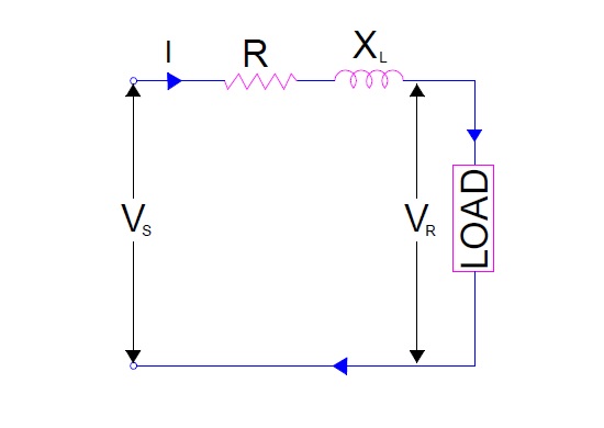
In the figure above,
R = Line Resistance
XL = Line Reactance
Vs = Sending end phase voltage
VR = Receiving end phase voltage
I = Line Current.
In electrical engineering, it is a good practice to draw phasor for a circuit. Therefore, we will draw the phasor of above circuit for evaluation transmission line performance. Let us consider line current I as reference and assume that it is lagging the receiving end voltage VR by an angle ØR for drawing phasor.
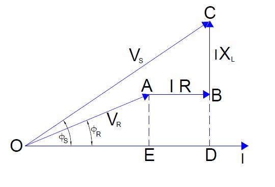
In the above phasor,
OA is receiving end voltage and leading the current I by an angle of ØR.
IR is the voltage drop in the resistance of line.
IXL is the voltage drop in the reactance of the line.
Therefore, sending end voltage must be the vector sum of receiving end voltage, voltage drop in resistance and reactance. Let’s calculate sending end voltage using phasor diagram.
In right angled triangle OCD,
OC2 = OD2 +DC2
= (OE)2 + (DB + BC)2
= (VRCosØR)2 + (AE + BC)2
= (VRCosØR)2 + (VRSinØR + IXL)2
But OC = Vs
Vs2 = (VRCosØR)2 + (VRSinØR + IXL)2
Therefore,
Vs = √[(VRCosØR)2 + (VRSinØR + IXL)2] …………………(1)
Calculation of Voltage Regulation
If receiving end voltage, line current and power factor at receiving end are known then
% Voltage Regulation = [(Vs – VR) / VR]x100 % where the value of Vs can be calculated from equation (1).
Calculation of Transmission Efficiency
Power delivered at receiving end = VRICosØR
Line Loss = I2R
Therefore input power = Loss + Delivered Power
= I2R + VRICosØR
% Transmission Efficiency η = Power Delivered / Power sent
= [VRICosØR / (I2R + VRICosØR)]x100 %
Calculation of Sending end Power Factor
Sending end power factor is calculated from the phasor diagram shown above. As clear from phasor the angle between the sending end voltage Vs and line current I is Øs, therefore CosØs will be the power factor at sending end.
Sending end power factor = CosØs
= OD/OC
= (OE + ED) / Vs
= (VRCosØR + IR) / Vs
In right angled triangle OCD,
OC2 = OD2 +DC2
= (OE)2 + (DB + BC)2 ,,,,
How OD=OE?… its not… OD=OE+ED or OD=OE+AB