Brushless Excitation System is a technology for providing the field current to the Synchronous Generator without using Slip Ring and Carbon Brushes. As this method of Excitation i.e. Brushless Excitation System do not use Carbon Brushes, therefore the losses because of contact resistance of carbon brushes is eliminated.
Also, in case of initial start up of Generator we don’t need to supply external power source to Brushless Exciter as is the case in Static Excitation System. Because in Static Excitation System the power for filed excitation is taken from the output of the Generator terminal through CT and PT. But in Brushless Excitation System we don’t need any start up power supply for field excitation (Why? Ask yourself after going through the whole post. I am sure you will be able to Answer.)
Brushless Excitation System consists of two major parts: Pilot Exciter and Main Exciter.
Pilot Exciter:
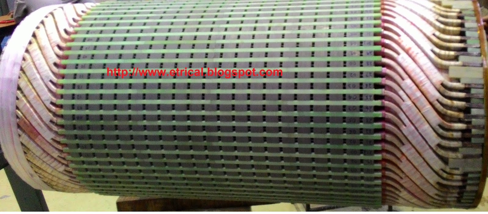
Pilot Exciter is Permanent Magnet, also called PMG (Permanent Magnet Generator) mounted on the rotor shaft. Armature winding of PMG is a stationary part which is mounted on Stator. Thus when rotor rotates, the filed flux created by Permanent magnet will also rotate and as Armature is stationary, there will be flux linkage in the Armature winding of PMG and an EMF will be induced across the terminals of Armature of Pilot Exciter. This Armature thus produces three phase AC power by using the mechanical energy of Rotor. This AC power from Pilot Exciter is then rectified by Thyristor Bridge. This DC is then feed to the field winding of Main Exciter which is wounded on Stator of main Exciter. Note that Permanent Magnet of Pilot Exciter is mounted on Rotor, Armature of PMG is stationary as it is wounded on Stator and Field winding of Main Exciter is stationary as it is also wounded to Stator of Main Exciter. Normally PMG has 16 poles, so the AC produced by PMG will be at a frequency of 400 Hz (f = PN/120, N =3000 rpm). Why?
Because of high frequency the ripple content in the rectified DC will be low. That is why PMG produces AC power at this higher frequency. Armature of PMG is shown in figure below.
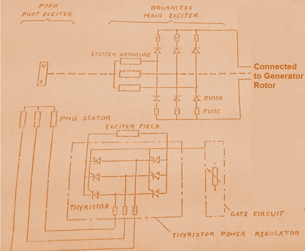
Schematic diagram of Brushless Excitation System is shown in figure below.
Main Exciter:
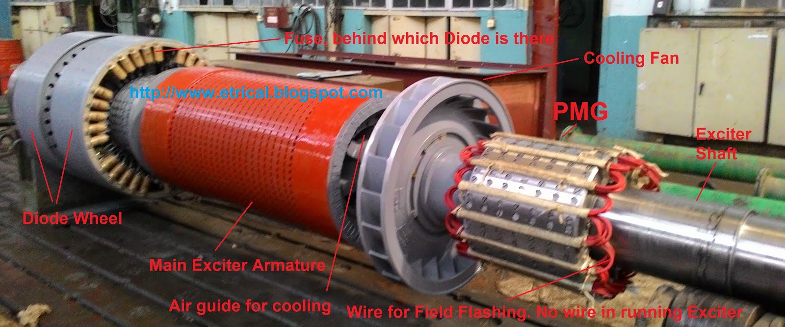
Main Exciter of Brushless Excitation System consists of Stator and Rotor part. Rotor of Main Exciter is coupled with the Rotor of Turbo Generator on which armature winding is wound. On Stator, filed winding is wound. Normally there are six poles on the field, so it will produce AC power at a frequency of 150 Hz. This AC power is then converted to DC by Diode Bridge. Diode Bridge is mounted on two wheels which in turn is mounted on the Rotor shaft. This wheel is called Diode Wheel. Both diode wheels are connected to complete a bridge rectifier arm. Figure of whole Brushless Excitation System is shown below.
For each arm of Diode, two fuses are connected as shown in the Schematic diagram of the Brushless Excitation System.
The above picture shows the whole Brushless Excitation System. Note that Brushless Exciter is manufactured and supplied separately. Then Turbo Generator and Brushless Exciter rotor is coupled at the Site. Form the figure, wire is wound on the PMG, actually it is wound for making the material permanent magnet by field flashing. Field flashing is done by applying 20,000-24,000 AT for fraction of second. Two poles, North and South pole is created on the PMG filed by field flashing. Moving a bit left from PMG, you can see a Fan and this is provided for cooling purpose. Brushless Exciter is normally air cooled. Thus this Fan forces the air to pass through the Air Guide (see in figure) and main Exciter Armature for cooling. Also from the figure, you can see small windows on Armature of Main Exciter, it is provided for cooling.
Now the question arises how to control the field current of Turbo Generator?
See the schematic diagram of Brushless Excitation System. Thyristor Power Regulator controls the DC output of Thyristor Bridge Rectifier. Thus by Thyristor Power Regulator / Automatic Voltage Regulator we control the field current to the Main exciter due to which we can control the AC output of Main Exciter and hence the DC output of Diode Bridge Rectifier which is feed to the Field winding of Turbo Generator Filed winding. By this way we control the field current input to the field wing of Turbo Generator.
Hope you enjoyed this post. If you have any doubt, please write in comment box. Thank you!!!
Dear Sir
Very good explain, How much voltage generate by PMG,Feed back in running condition for regulation of Voltage taken by PMG Or through Alternator voltage .
pl reply same board or by mail [email protected]
dear sir,
if pmg fail to build up emf at starting , how can i give excitaion to field flashing of alternator
please give me answer on mail
-RAGAB
Say:
dear sir,
Why used DC IN exiter
please give me answer on mail
DC is used in the main exciter to provide generator field excitation.
dear sir
how can we estimate the rotor current of the synchronous exciter (with rotary armature)?
If high frequency reduces ripple then why not go for more than 400Hz?
Thank you for such a nice explanation. Please also provide necessary data.
Thank you!
What is the requirements of main exciter if we feed rectified dc output from AVR to gen field directly through diode bridge?
What is the connection of winding of main exciter ?
220volts ac supply from PMG comes to excitation panel where it is rectified by thyristor bridge. Thyristor bridge is controlled depending on firing angle. This firing angle is controlled by a PID controller (Auto/manual) channel depending on error between generator and grid voltage. Voltage produced by this source is just a control D. C. signal to drive the field of main excitor. Now main exciter output ac voltage will also be automatically controlled (as field is controlled). This 3 phase output from main excitor is rectified by uncontrolled rotating diode bridge and applied to field winding. Or you can say that main excitor acts just like amplifier.
Without any supply rotor is rotated?
Rotor of turbo generator is rotated by the turbine.
Sir why we are using main exciter directly output of thyristor ie 3phase DC is directly not given to generator why we are using main exciter????
This is because the arrangement need to made rotating. The armature of pilot exciter is stationary which is fed to the stationary field winding of main exciter through AVR. If you don’t do so, the arrangement will not be rotating. Got the point?
I don’t understand what you want to clear. The shaft rotational energy or torque will be supplied by turbine. Now at engineering stage you have a choice to choose whether you want Static excitation or Brushless excitation. In Brushless excitation system PMG (mounted on the main shaft at non driving end) generates 220volts, 400hz ac power. This power is routed through AVR and converted in to controlled DC output. This controlled DC voltage is applied to stationary field winding of Main exciter. In main exciter controlled AC voltage will be generated in armature winding mounted on rotor. This ac voltage is rectified by diodes mounted on rotating diode wheel. This rectified DC voltage is applied to roter winding of Main Generator. The induced voltage in stator winding is nothing but the output voltage of generator.
Correct! So, it is already clear to you. However, if you want to add something more, you are most welcome.
Sir, how can we determine thepower rating of pre-exciter require for main exciter and for main generator and their electrical parameters if they are not provided by manufacturer
Alternator running with some load, pmg got fault. At that time without failure of generation, can we do anything
Alternate solutions are there any…
It is not recommended. Better, you consult OEM regarding online maintenanace.
Just i have a doubt with out loss of generation, is there any possibility
I think, no option for online maintenance. Kindly share if you get to know any method for the same. Thank you in advance.
Dear all I have develop a new method for brushles excitation which have following advantages w.r.t conventional brushles excitation.
1) 30 times light in weight as compare to conventional brushless excitation.
2)have negligible mechanical losses
3) there is no need for pilot excitor.
But I have looking for a brushless excitor manufacturing company to develop this excitation system.
Dear Sirs.
I have a major issue with my genset (MAN diesel engine with 950 kva Reliance generator) and I cannot find the problem. My engine is seeing increased torque without the proportionate current output. Simply put at maximum engine output (based on engine governor position and fuel pump control linkage) I am only getting around 44% of maximum current from the generator. Could the problem be in the excitor? What else would cause an increase in generator torque without the respective power output? I thank you in advance!