This article explains the definition and working principle of a Capacitive Transducer. Apart from this, Advantage & Disadvantage and application of Capacitive Transducer are also discussed in detail.
Definition:
Capacitive Transducer is a device which changes its capacitance with change in the physical phenomena to be measured. It is a passive transducer which required external source of supply to function. The transduction element of capacitive transducer is a capacitor which may be a parallel plate, cylindrical or angular capacitor. It is commonly used for the measurement of linear displacement.
Working Principle of Capacitive Transducer:
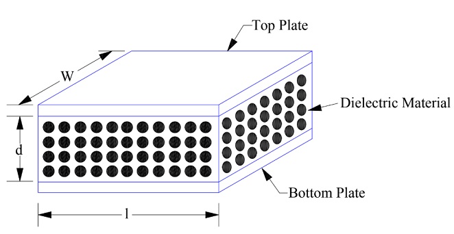
The working principle of capacitive transducer is based on the capacitance of parallel plate capacitor. The capacitance (C) of a parallel plate capacitor with plate area A separated by distance d is given as below.
C = ƐoƐrA / d ………….(1)
Where Ɛo and Ɛr are the permittivity of free space and the relative permittivity of the dielectric material of capacitor.
A typical parallel plate capacitor with a dielectric material in between the plate is shown in the figure below.
The capacitive transduce works on the principle that the capacitance can be varied by varying the following:
- Area of plate
- Separation between the plates
- Changing the dielectric material between the plates.
In capacitive transducer, the above changes are caused by physical variables like linear displacement, angular displacement, force, pressure and level of liquid. Notice that when the liquid level changes through the capacitor, the dielectric medium is changed and hence the capacitance will change.
The change in capacitance may be measured by bridge circuit. The output impedance of capacitive transducer is given as Xc = (1/2πfC) where f is supply frequency and C is capacitance. Assuming frequency if supply to be constant, the output impedance is a function of capacitance and hence change in physical variable results in corresponding change in Xc.
The capacitive transducer is mostly used for the measurement of linear displacement. For this purpose, following effects are utilized:
- Change in capacitance due to change in overlapping area of plate
- Change in capacitance due to change in separation between the plates.
Transducer using change in Area of Plate:
As we know that, capacitance of parallel plate capacitor is directly proportional to the area of plate, therefore, this property can be employed to measure the displacement. Above all, the response of such type of transducer will be linear which simply means that physical change will have a linear relation with the measured capacitance.
For the measurement of displacement using capacitive transducer, one plate of parallel plate capacitor is kept fixed while the other plate is allowed to displace. An elementary diagram of this transducer is shown in figure below.

Let us assume that the width of plate is W and the length at any time t is X. Thus, the area of plates of parallel plate capacitor so formed at time t will be (WX). Therefore, the capacitance at any time t is given as below.
C = [ƐoƐr(WX) / d]
From the above expression, it is clear that the displacement X is directly proportional to capacitance C. Hence, measurement of capacitance will directly tell us the magnitude of displacement. Thus, physical quantity displacement is converted into electrical quantity capacitance which is the required function of a transducer.
Sensitivity of a device is the rate of change of output with respect to input. Thus, the sensitivity of capacitive transducer will be the rate of change of capacitance (C) with respect to displacement (X). Let us now find this sensitivity (S).
S = dC / dX
= ƐoƐrW / d
From the above expression, it may be stated that the sensitivity of a capacitive transducer is constant and depends on the width & separation between the plates. This is a great feature of capacitive transducer and exploited for measurement of linear displacement ranging from 1 mm to 10 mm. The accuracy is as high as 0.005%.
The principle of change of capacitance with change in area is also employed for the measurement of angular displacement. Figure below shows a two-plate capacitor in which one plate is fixed and the other can rotate.
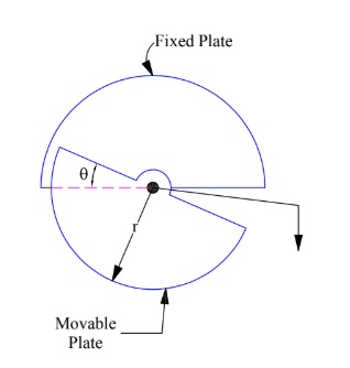
The angular displacement changes the effective area between the plates and hence, a corresponding change in capacitance. Let, at any time t, the angular overlapping position is Ɵ. Since the area of entire plate is (πr2/2) for angular overlapping of π radian, therefore, the area (A) of plate for angular overlapping of Ɵ radian will be
A = (πr2/2π)Ɵ = Ɵr2/2
Capacitance = [ƐoƐrƟr2/ (2d)]
From the above expression, it is obvious that the capacitance is directly proportional to the angular movement. Hence, measurement of capacitance is a direct indication of angular movement. The graph between the capacitance and angular position is a straight line and shown below.
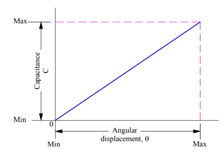
It should be bear in mind that, above mentioned capacitive transducer can only be used for measuring angular position from 0 to 180°.
Transducers Using Change in Distance between the Plates:
A Capacitive Transducer can also be designed to respond to linear displacement by attaching one of the plates of capacitor to the moving object and keeping the other plate fixed. When the object moves, the distance between the plate changes and hence the capacitance changes. The variation of capacitance with separation between the plates is evident from (1). It can easily be seen from (1) that capacitance is inversely proportional to the distance between the plates.
An elementary diagram of a capacitive transducer utilizing principle of change of capacitance with change in distance between the plates is shown in figure below.
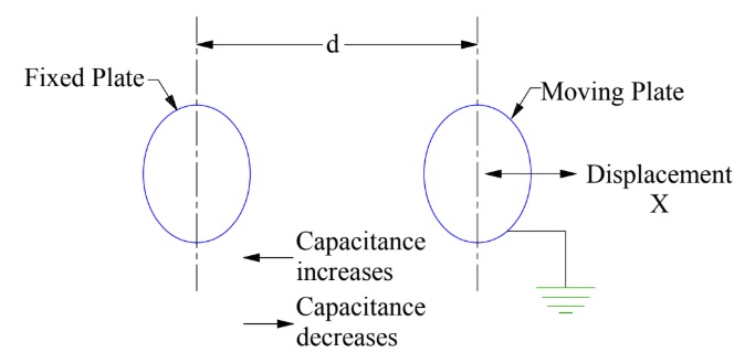
The separation between the plate is x at any time t. Hence, capacitance is given as
C = ƐA/x
The characteristics of this transducer is, thus, non-linear. Actually, it is hyperbolic as shown below.
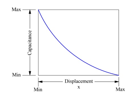
The sensitivity of this transducer is calculated as below.
S = dC/dx
= -ƐA/x2
The sensitivity of this transducer is not constant rather it varies with the separation between the plates. In fact, the lesser the distance x, the more is the sensitivity. This means that, the device will respond for lower value of displacement. It will not respond to higher value of displacement. This is the reason; this type of capacitive transducer is used for applications requiring measurement of extremely small displacement.
You might think that this is a disadvantage. But actually, it is not so. Just compare the sensitivity of capacitive transducer utilizing change in area and change is distance between the plate. The sensitivity is constant for the former while the same is higher for extremely small displacement. This means, if we want to measure very very small displacement, transducer utilizing change in separation between plates will be more responsive i.e. change in capacitance will be more for an extremely small change in displacement between the plates. This is advantageous for measurement of small displacement. Any doubt? Please write in comment box.
Transducer using change in Dielectric Constant:
A capacitive transducer may use the principle of change in dielectric constant to achieve variable capacitance. This is quite obvious if you refer (1). The capacitance of parallel plate capacitor is directly proportional to dielectric constant (Ɛ) for a given plate area and separation. This principle is also utilized in capacitive transducer for the measurement of linear displacement.
An elementary diagram using change in capacitance due to change in dielectric constant is shown in figure below.

The plates of capacitor are fixed. However, a moving object having some dielectric constant Ɛr is moving into the plates. We want to measure the displacement of the object. At any intermediate stage, let the l2 length of object is inside the plates. Therefore, up to l2 length, the capacitor is filled up with dielectric having dielectric constant Ɛr whereas l1 length have air. The capacitance in this combination can be found as shown below.
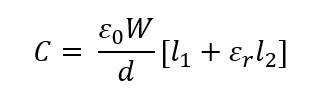
From the above expression, it is clear that, as the object moves into the capacitor, the value of l2 increases and hence the capacitance C increases. By measuring this capacitance, the linear displacement can be predicted.
Advantage and Disadvantage of Capacitive Transducer:
Advantage:
The major advantages of capacitive transducer are listed below:
- This transducer requires very small force to operate and hence utilized in small systems.
- They are very sensitive. The accuracy is as good as 0.005%.
- The loading effect is minimum in this transducer due to high input impedance.
- A resolution of the order of 2.5×10⁻³ can easily be obtained using these transducers.
- Measurement of Inductive Transducer is affected by the stray magnetic field whereas a capacitive transducer is not affected.
- The power requirement of capacitive transducer is less as they require less force to operate.
Disadvantage:
The principle disadvantages of a capacitive transducer are mentioned below:
- Capacitive Transducer requires its metallic part to be insulated from each other. If they get short, the value of capacitance will become zero. Above all, to avoid the effect of stray capacitance on the measurement, the frame of this transducer must be earthed.
- The Capacitive Transducer shows non-linear behavior may a times because of the effect of edges. Guard rings are used to eliminate this effect.
- The cable connecting to the transducer is also a source of error when measuring small physical changes. The cable may be source of loading resulting in loss of sensitivity. Also loading makes the low frequency response poor.
- The capacitance may change due to dust, moisture etc.
- They are temperature sensitive and therefore, any change in temperature adversely affects their performance.
- The instrumentation circuitry used with capacitive transducer is quite complex.
- The output impedance (1/2πfC) of capacitive transducer is quite high due to lower value of capacitance. This leads to loading effect. The output impedance depends on the frequency of signal used for the measurement of capacitance. For capacitance lying between 10-500 pF, the frequency used are such that they give an output impedance in the range of 1 kΩ to 10 MΩ. This high value of output impedance means that the insulation resistance must be kept high to avoid the shunting of capacitance unduly and reducing the sensitivity.
Application of Capacitive Transducer:
The major applications of a capacitive Transducer are listed below.
- Capacitive Transducer is mostly used for the measurement of linear and angular displacement. They are very sensitive and can measure extremely small displacement of the order of 10-6 mm.
- They are also used for the measurement of force and pressure. Force and pressure are first converted into linear displacement and then the displacement is measured by capacitive transducer.
- Capacitive Transducer can be directly used for pressure measurement where change in pressure results in corresponding change in dielectric constant of medium between the plates of capacitor.
- Dielectric constant of gases changes with humidity. Therefore, a capacitive transducer can measure the humidity in gases by employing the change in capacitance due to change in dielectric constant principle.
- It can also be used to measure liquid level, volume, density etc. However, a mechanical modifier is required for the measurement of these parameters.
👏👏👏👏👏