Definition:
A transducer utilizing piezoelectric element to convert mechanical motion into electrical signal is called a piezoelectric transducer. This transducer works on the principle of Piezoelectric Effect. It is an active transducer.
Piezoelectric Material and Piezoelectric Effect:
A piezoelectric transducer uses a piezoelectric material as a transduction element. A piezoelectric material is one in which an electrical potential difference appears across a certain surface of a crystal if the dimension of the crystal is changed by the application of force. This potential difference appears due to displacement of charge. The process is reversible which means if potential difference across some specified surface is changed, the dimension of the piezoelectric material will also change. This effect is known is Piezoelectric Effect. Elements exhibiting qualities are known as electro-resistive elements.
Rochelle Salt, Ammonium Dihydrogen Phosphate, Lithium Suphate, dipotassium tartarate, quartz and ceramic are some common example of piezoelectric material. Basically, there are two types of piezoelectric materials: Natural and Synthetic.
A natural piezoelectric material is one which occurs in nature and can be used as such. However, synthetic piezoelectric materials are those materials in which piezoelectric properties are not found in their original state but these properties are produced using special techniques such as polarizing treatment.
Quartz and Ceramic are examples of natural piezoelectric material whereas materials like lithium sulphate, ethylene diamine tartarate belong to the synthetic group.
Working Principle of Piezoelectric Transducer:
The working principle of a Piezoelectric Transducer is based on the fact that when a mechanical force is applied on a piezoelectric crystal, a voltage is produced across its faces. Thus, mechanical phenomena is converted into electrical signal. No external supply is required for this transducer to work and hence it is an active transducer.
Piezoelectric Tansducer responds to the mechanical force / deformation and generate voltage. There may be various modes of deformation to which these transducers can respond. The modes can be: thickness expansion, transverse expansion, thickness shear and face shear.
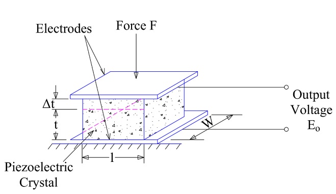
In a piezoelectric transducer, a piezoelectric crystal is sandwiched between the two electrodes. When a mechanical deformation takes place, it generates charge and hence it acts as a capacitor. A voltage is developed across the electrodes of the transducer which can be measured and calibrated with the deforming force to directly measure the mechanical deforming force. Figure below shows a simple piezoelectric transducer.
It should be noted that, piezoelectric effect is direction sensitive. This means that, the polarity of charge will not be same for a tensile and compressive force. The polarity of voltage induced due to a tensile force will be opposite to the polarity of voltage produced due to a compressive force.
The magnitude and polarity of induced charge on the electrodes are directly proportional to the applied force and its direction. Let the applied force be F, then the charge induced will be given as
Q = kF ……….(1)
where k is constant of proportionality. This constant is nothing but the charge sensitivity of the piezoelectric material. It is constant for a given material and defined as the charge generated per unit applied force. Its unit is (Columb / Newton)
Assuming the surface area of electrode, separation between the electrodes be A and d respectively, the charge generated on each of the electrode of piezoelectric transducer is given as below.
Q = CV
where C is capacitance formed by the electrodes and the piezoelectric material
C = ƐA / d
Therefore,
Q = ƐAV / d ………….(2)
From (1) and (2),
kF = ƐAV / d
F = (ƐAV) / (dk)
Carefully observe the above expression; Ɛ, A, d and k are constant for a given piezoelectric transducer. This essentially means that, magnitude of applied force is directly proportional to the output voltage across the electrodes.
Thus, by measuring the value of voltage across the electrodes of piezoelectric transducer, we can find the value of mechanical force. Hence, mechanical force converted into electrical signal which is the whole & sole requirement of any transducer.
Modes of Operation of Piezoelectric Crystal:
Piezoelectric crystal can be used in many modes. There modes are:
- Thickness shear
- Face Shear
- Thickness Expansion
- Transverse Expansion
These modes are shown in figure below.

Each of the above mode can be converted into electrical signal by using piezoelectric transducer. By cementing two crystals together so that their electrical axes are perpendicular, “Benders” or “Twisters” can be produced. This means that a bending motion applied to a bender produces an output voltage. Similarly, a twisting motion applied to a twister produces a voltage output. Benders and twisters are shown below.

Properties of Piezoelectric Crystal:
The main properties of piezoelectric material for its suitability for use in piezoelectric transducer are stability, output insensitivity to temperature & humidity and ability to be formed in most desirable shape.
Quartz is the most stable piezoelectric crystal. However, its output is very small. On the other hand, Rochelle Salt provides highest output but its main drawback is that it can only be used over a limited temperature range (up to 45°C only) and it has to be protected from moisture.
Barium Tartarate has the advantage that it can be formed into various shapes and sizes. Its dielectric constant is also high (hence Capacitance C will be high which will result in higher output voltage). Natural crystal posses the advantage that they have higher mechanical and thermal stability, can withstand higher stresses. The synthetic material has generally higher voltage sensitivity.
Equivalent Circuit of Piezoelectric Transducer:
The basic electrical equivalent circuit of a piezoelectric transducer is shown in figure below.
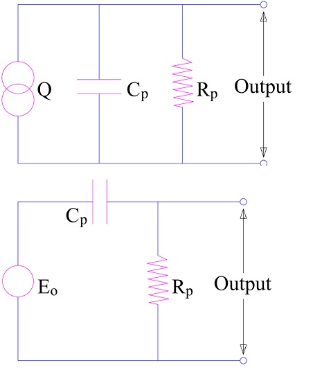
Following points may be noted from the equivalent circuit of piezoelectric transducer:
- Source is a charge generator whose value is equal to dF.
- The charge generated is across the capacitance Cp of the crystal and leakage resistance Rp.
- The charge generator can be replaced by an equivalent voltage source having a voltage of Eo = Q/Cp = dF/Cp
Application / Usages of Piezoelectric Material and Transducer:
The application or usages of piezoelectric material and transducer are listed below:
- Quartz is commonly used for stabilizing electronic oscillators due to its high stability.
- Piezoelectric Transducer is mainly used in dynamic measurements. The voltage developed by application of strain is not held under static condition. Therefore, these transducers are used in the measurement of quantities such as Surface Roughness, acceleration (called accelerometer) and vibrations.
- Ultrasonic generator also uses Barium titanate which is a piezoelectric material. Such materials are used in industrial cleansing apparatus and also in underwater detection system known as sonar.
i asked abt the operation of piezoelectric transducers but didnt get exact answers…
I think this is best website for electric engineering students.
Thank you! Kindly share as it motivates us.