What is a Chopper?
A chopper is a static device that converts fixed DC input voltage to a variable DC output voltage. It is basically a high speed ON/OFF semiconductor switch. It may be thought of as DC equivalent of an AC transformer since they behave in an identical manner.
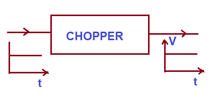
Chopper is fed through a constant DC voltage source and its output is variable DC voltage. The average value of output DC voltage may be less than or higher than the input DC voltage source. A simple diagram defining the chopper is shown below.
A chopper is a DC equivalent to an AC transformer having continuously variable turn ratio. Like a transformer, a it can be used to step-up or step-down the fixed DC input voltage. On this basis, there are two types of chopper: Step-up and Step-down Chopper. A chopper whose average value of DC output voltage is more than the fixed DC input voltage is called Step-up Chopper. While, a chopper whose average value of DC output voltage is less than the DC input voltage is called Step-down chopper.
Working Principle of Chopper:
A chopper is a high speed ON/OFF switch. It connected source to load and disconnects the load from the source at a fast speed. Figure below represents the simple circuit to show its working principle.
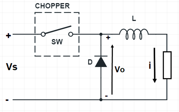
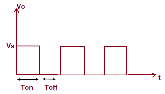
In this circuit, the switch SW is chopper. This switch can be made ON and OFF at a very high speed. In this way, the load may be connected and disconnected from the supply source Vs. When the switch is ON, the load voltage is equal to the source voltage Vs and when the switch is OFF, load voltage becomes equal to ZERO. Thus, a chopped voltage across the load is obtained. The output voltage i.e. voltage across the load is shown in figure below.
It should be noted here that, when the switch SW is made OFF, the load current finds its path through free wheeling diode D. Therefore, diode D acts as a short and hence the voltage across the load becomes zero. Inductor in the chopper is an essential thing. This inductor makes diode D forward biased when the switch SW is OFF.
It should also be noted that, even though the switch SW is made OFF, the load current doesn’t becomes ZERO. Rather, it flows through the free wheeling diode, inductor L and load. In fact, the load current is continuous as shown below.
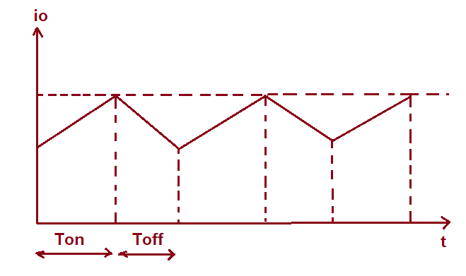
It may be seen from the above waveform of output current of chopper that, during ON time, the current rises whereas during OFF time, the load current io decays.
The time for which chopper connects the load from source is called ON time i.e. TON. Whereas, the time for which load is disconnects from source is called OFF time i.e. TOFF.
Duty Cycle:
Duty cycle of chopper is defined as the ratio of ON time to the total time period. It is denoted by symbol α. Total time period is the sum of ON and OFF time.
Duty Cycle = TON / (TON+TOFF)
Assuming (TON+TOFF) = T, duty cycle is given as below.
Duty Cycle, α = (TON / T)
Calculation of Output Voltage:
The average output voltage of chopper may be find from the output voltage waveform. It is clear from the o/p voltage waveform that, voltage Vo is available only for TON time period in the total time (TON+TOFF). Therefore, avergare ouput voltage Vo may be calculated as shown below.
Vo = TON Vs / (TON+TOFF)
But, TON / (TON+TOFF) = α
Hence,
Vo = αVs
Thus, the output voltage may be controlled by controlling the duty cycle. This duty cycle may be controlled in various ways which we will discuss in the next post. From the expression of ouput voltage, it is also clear that, the output voltage is independent of the load current.
The expression for chopper output voltage may also be written as below.
Vo = TON Vs / (TON+TOFF)
= Vs TON / T
Assuming 1/T = Chopping frequency
Vo = f Vs TON