Definition:
Ideal Transformer is a hypothetical transformer having infinite permeability core and zero core loss and ohmic loss. An ideal Transformer does not exist in reality. This is just a hypothetical transformer for sake understanding the actual transformer.
Properties of Ideal Transformer:
Following assumption are made to define an ideal transformer:
- Winding Resistance is negligible.
- All the flux set up by the primary winding links the secondary winding. This means, the leakage flux is zero. This is also evident from the assumption that transformer core is having infinite permeability. As permeability of core is infinite, the leakage flux will be obviously zero.
- The core losses viz. hysteresis and ohmic loss is assumed zero.
- The core has constant permeability. This means that the B-H curve of core is linear.
Mind that above mentioned points are assumptions. It is not property as the ideal transformer does not exists. Hence it is better to say assumption rather than saying properties. For a practical transformer, none of the above assumptions holds good. There is always a deviation.
Working of Ideal Transformer
Consider the ideal transformer shown in figure below.
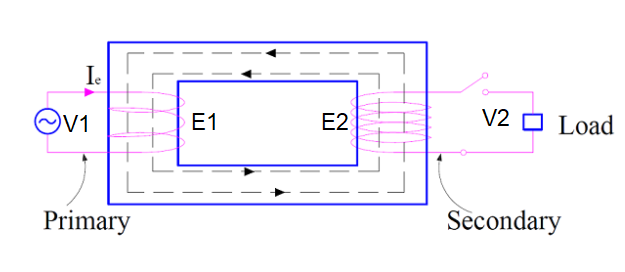
The voltage source V1 is connected to the primary winding. Magnetizing current Ie is being drawn by the transformer to create required magnetic flux (ø) in the core. This flux links with the secondary winding to generate an emf E2 as per Faraday’s Law. EMF E1 is also generated in the primary by the current Ie flowing through it. It should be noted here that, there is no leakage of flux, hence entire flux created by the primary links with the secondary.
Since, the winding resistance of ideal transformer is assumed zero, therefore the source voltage V1 should be equal to the self-induced voltage E1 in primary.
V1 = E1
Similarly, the load voltage V2 in secondary side is equal to E2.
V2 = E2
As, the losses in ideal transformer is assumed zero, this means input power is equal to the output power.
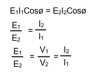
Since E1 and E2 are directly proportional to number of turns in primary and secondary respectively, therefore
E1/E2 = N1/N2
Therefore, transformation ratio of transformer is given as below.

Phasor Diagram of Ideal Transformer:
The phasor diagram of an ideal transformer under no load condition is shown below. Since the core loss of transformer is zero, the magnetizing current Im is in phase with the core flux (ø). This can also be understood as flux is directly proportional to mmf (N1Im), hence both the flux and magnetizing current are in phase.
In other words, the primary winding is purely inductive, hence current drawn by primary (Im) will lag supply voltage (V1) by 90 degree.

The primary and secondary winding is assumed purely inductive (winding resistance is zero), hence the induced emf E1 and E2 in both the primary & secondary winding will lag by 90 degree with respect to the core flux ø. However, the supply voltage V1 will be opposite to the induced emf E1 as the entire supply voltage is dropped across the self-induced emf E1.
plz add a table of content topic wise so that it would be easier to study serially and conceptually like a book from basics to advanced level rather than searching and studying randomly
I will try to figure out the solution of your problem. Till then, kindly bear with us.