The main difference between lap and wave winding is the manner of connecting the armature winding coil end to the commutator segment. In lap winding the top and bottom coil ends are connected to adjacent commutator segment whereas in wave winding, they are bent in opposite direction and connected to commutator segments which are approximately two pole pitches apart.
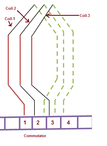
Generally in two layer winding, two coil sides of two different coils are accommodated in a particular slot. One coil side is housed at the top of the slot whereas other at the bottom of the slot. In general, if one coil side of a particular coil is placed at the top of one slot then its other coil side is placed in the bottom of another slot. Figure below shows a simplex lap winding.

In the above figure, top coil and bottom coil end are shown in red and green color respectively. It can easily be observed that one coil side of coil-1 is placed at the top of one slot then its other side is placed in bottom of other slot. This pattern is maintained for all other coils. For lap winding, that top coil end and bottom end of coil-1 are connected to commutator segment 1 and 2 respectively. Similar is the case for coil-2 and coil-3.
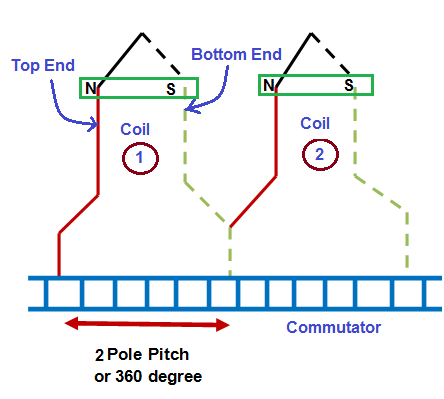
Figure below shows a wave winding.

It can be seen from the above wave winding arraignment that, the two coil ends are bent in opposite direction and connected to commutator segments which are approximately 360 electrical degrees apart in space.
Due to difference in connection of coil ends to commutator, there are two numbers of parallel paths in wave winding whereas the number of parallel path in lap winding is equal to number of poles.
Some of the major difference between lap and wave winding are tabulated below.
| Sr. No. | Lap Winding | Wave Winding |
| 1) | The number of parallel path in lap winding is equal to the number of poles. | The number of parallel path is always equal to 2. |
| 2) | The number of carbon brush in lap winding is equal to the number of poles. | The number of carbon brushes requirement in wave winding is two due to two parallel paths. However, it can be fitted with as many brushes as the number of poles. |
| 3) | Equalizer ring is required for obtaining better commutation. | No need for equalizer ring. |
| 4) | Lap winding are used for low voltage and high current rating machines. | Wave connected winding is required for high voltage but low current rating machines. |
| 5) | Since emf generated in DC machine = (ØZPn / a) where P,n and ‘a’ are number of poles, speed in rps and number of parallel path. But in lap winding, number of parallel path ‘a’ = P; therefore, the emf generated in lap winding = ØZn.
Thus emf generated in lap winding is independent of number of poles. |
In wave winding, the number of parallel path = 2, therefore emf generated = ØZPn / 2). Thus the emf generated depends on the number of poles. |
| 6) | The conductor current in each parallel path is (I/a). | The conductor current in each parallel path is (I/2) in wave winding. |
| 7) | If lap coils are traversed (refer figure for lap winding), the movement is forward and backward alternatively. | If wave coils are traversed (refer figure for wave winding), the movement is forward only. |
| 8) | The commutator pitch for lap winding is always 1. | The commutator pitch for wave winding is almost equal to 2 pole pitch i.e. 360 electrical degree. |
| 9) | – | Wave winding is more advantageous over lap winding. |
| 10) | It is more costly due to requirement of equalizer ring and more carbon brushes. | It is comparatively cheap. |
One pole pitch is 180 degrees electrical. It’s not 360 as mentioned in your post.
Thanks, i was looking for this article
What Is Lap winding and wave winding in Hindi