Electrical and Mechanical angles are frequently used in the study of Electrical Machine theory and therefore it is very important to have a crystal clear concept of these two terms and the relationship between them. In this post we will also discuss about the Synchronous Speed and their relationship with Electrical and Mechanical angle.
As we know that emf is induced in a conductor is given by Faraday’s Law of Electromagnetic Induction which can be expressed as below.
The magnitude of emf generated in a conductor of length L moving at a speed of v perpendicular to the Magnetic Field B is given by
E = BLv
For better understanding of Faraday’s Law and generation of emf in a Conductor, read How does Motional EMF Produced?
Thus from the above expression of emf, we observe that the waveform of emf depends on the wave shape of Magnetic Field. If the waveform of Magnetic Field is square then the generated or induced emf in the conductor will also be square. Likewise if the waveform of Magnetic Field is Sinusoidal then waveform of E will also be sinusoidal.
Consider a two pole machine as shown in figure below. Suppose a conductor is rotating at a constant angular velocity. When the conductor is at a, emf induced in the conductor is zero as the magnetic field at a is zero.
Must Read Advantages and Disadvantages of Short-Pitch Winding
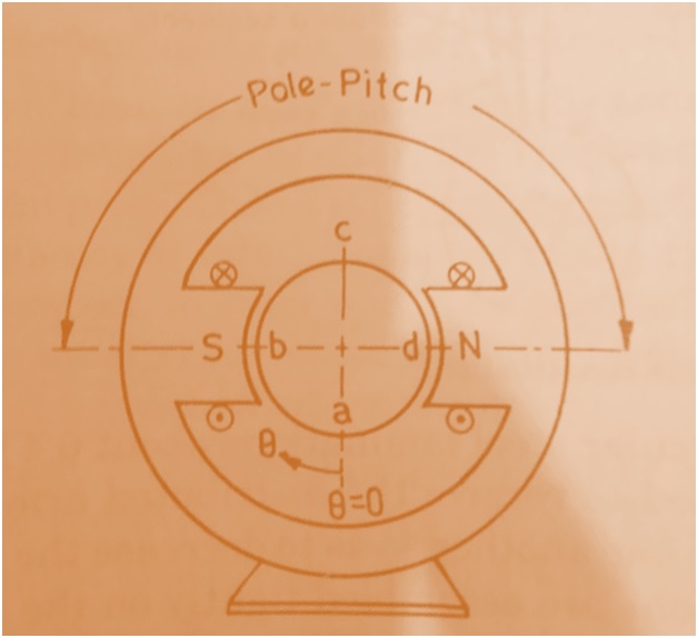
Similarly, when conductor is at b, the emf induced in maximum as magnetic field is maximum at b. Let us consider this magnetic field at b to be positive i.e. magnetic field entering the south pole of stator to be positive then the for the whole rotation of the conductor, the waveform of emf induced will be as shown in figure (a) below.
Mind that the waveform of magnetic field as well as the induced emf are same as discussed earlier in the post. Thus one complete revolution of conductor results in one complete cycle of induced emf. In other words, we can say that 360° mechanical rotation of conductor results in 360° change in the induced emf for two pole machine.
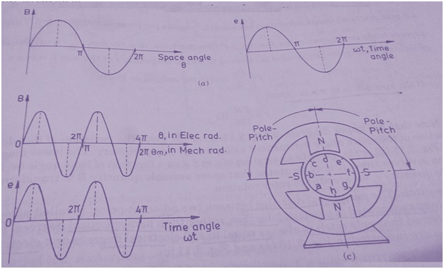
Now, assume that the same conductor in now moving at a constant angular speed but in four pole machine as shown in figure above. Here when the conductor is at a, the induced emf is zero as magnetic field at a is zero. Similarly for different positions of the conductor, the magnitude of induced emf with sign is tabulated below for the sake of better understanding.
|
Sr. No.
|
Position of Conductor
|
Value of Magnetic Field
|
Value of Induced emf
|
|
1)
|
b
|
+Maximum
|
+Maximum
|
|
2)
|
c
|
Zero
|
Zero
|
|
3)
|
d
|
-Maximum
|
-Maximum
|
|
4)
|
e
|
Zero
|
Zero
|
|
5)
|
f
|
+Maximum
|
+Maximum
|
|
6)
|
g
|
Zero
|
Zero
|
|
7)
|
h
|
-Maximum
|
-Maximum
|
The above values of the induced emf in the conductor when plotted with the rotation results in the waveform shown in figure (b) above. Thus we observe that, two cycles of emf is generated in one complete revolution of conductor. Therefore, though the mechanical rotation of conductor is only 360° but the electrical rotation is two times i.e. 720°. This point must be noted and carefully understood.
Thus based on the above two cases, we can say that P/2 cycle of emf is generated in one revolution for a P pole Electrical Machine and hence we can write the relationship between the Electrical and Mechanical angles as
Ɵelect = (P/2) Ɵmech …………………..(1)
Hope you understood how the relationship between the Electrical and Mechanical angles derived and what their bases are.If you still have doubt, feel free to write in comment box.
Now we will understand the how the synchronous speed is related with the relationship between the Electrical and Mechanical angles?
From the relationship between the Electrical and Mechanical angles,
Ɵelect = (P/2) Ɵmech
Differentiating both sides with respect to time, we get
d(Ɵelect) / dt = (P/2)d(Ɵmech) / dt
⇒ ωelect= (P/2)ωmech
But we know that, ω = 2πf
⇒ 2πfelect= (P/2) 2πfmech
⇒ felect= (P/2) fmech
But mechanical frequency simply means the number of revolution of conductor per second. If we take number of revolution per second to be n then,
f = Pn/2
where f = frequency of generated emf.
Again, if we take number of revolution of conductor per minute to be N then number of revolution per second n = N/120, therefore
Frequency of emf f = PN/120
This frequency f is known as synchronous frequency. That’s all. So simple?? Please write your views and comments. Thank you!
"if we take number of revolution of conductor per minute to be N then number of revolution per second n = N/120, therefore"
In this part the revolution per second should be N/60.