Generally earth faults are Single Line to Ground (SLG) and Line-Line to Ground (LLG) faults. Earth faults are characterized by the presence of Zero Sequence Curren I0. Since, except for unbalance, normal system operation is not having Zero Sequence Current I0, much more sensitive pick-up is possible for earth fault by using zero sequence current component I0 = (Ia + Ib + Ic) / 3 and declaring a fault if I0 exceeds a threshold.
We know that I0 = (Ia + Ib + Ic) / 3
However, in a system with multiple sources or parallel paths, we require earth fault relays to be directional as discussed in earlier post How to Incorporate Directional Featurein a Relay.
As we discussed in earlier post How to Incorporate Directional Feature in a Relay, that for making a Relay directional we need Reference Phasor. The reference phasor is called as Polarizing Quantity. For ground fault relaying both Voltage and Current Polarization can be used.
We will consider each Voltage and Current Polarization separately for Earth Fault Protection.
Voltage Polarization:
Let the system be initially unloaded and a ground fault occur on phase A.
Therefore Ib = Ic = 0 and Ia = 3I0.
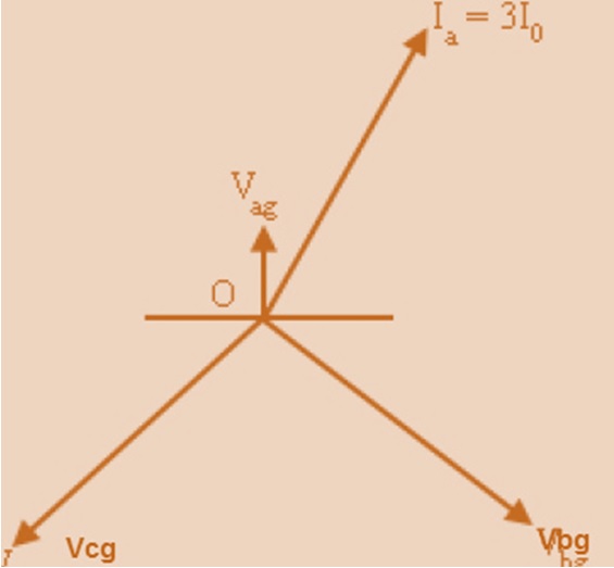
For Single Line to Ground fault there is a drop in voltage of phase A while phase B and C voltages remain unchanged. Phasor diagram for Voltage and current for SLG fault can be drawn as below.
Voltage and Current Phasor under Single Line to Ground Fault:
In the phasor diagram only 3I0 is shown as Ib = Ic =0 and Ia = 3I0 for Single Line to Ground fault.
Now we will find the Zero Sequence Voltage under the fault.
As V0 = (Vag+Vbg+Vcg)/3, phasor sum of Va,Vb and Vc is to be taken.
3V0 = Vag+Vbg+Vcg, phasor sum
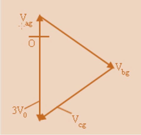
From phasor diagram it is clear that Zero Sequence Voltage 3V0 is in phase opposition with Vag (Phase Voltage of A). Therefore it is appropriate to take -3V0 as a reference phasor.
In normal power system V0is not present but available only during the fault. Let the maximum torque be drawn at 60 degrees lag with respect to -3V0 phasor as shown in figure below.

As we know that Zero Torque Line is perpendicular to the Maximum Torque Line, therefore we draw Zero Torque Line as shown in figure above.
It is then clear that zero Torque Line which separates the plane into Operate and Do Not Operate zone leads -3V0by 30 degrees. Thus, for fault in the correct region, 3I0 lags -3V0 hence falls in operate region. If fault is behind the relay, 3I0 will lead -3V0 by about 45 to 60 degrees and hence will lie in do not operate region. Hence, earth fault directional unit will not pick-up.
Current Polarization:
For providing direction feature in earth fault relay we can also use current as refrenec phasor which is called current polarization. It is an alternative for voltage polarization. It does not require an additional Potential Transformer (PT).
For balanced system,
Ia+Ib+Ic = 0, phasor sum is taken here.
Therefore, I0 = (Ia+Ib+Ic)/3 = 0 which means absence of Zero Sequence Current in balanced system.
During ground fault say at phase A, 3I0 flows from ground to neutral of a Wye connection of Transformer. If we assume for simplicity that Ib = Ic = 0, then 3I0 and Ia are in phase. This indicates that directional unit for ground relay should pick-up as Ia is in phase with 3I0. Thus we place maximum torque line at zero degrees with respect to I0 phasor. The corresponding Operate and Do Not Operate zones are marked in figure below.
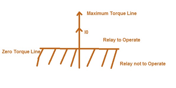
If fault is behind the relay, then the Ia will fall in Do Not Operate region and hence relay will not pickup as Zero sequence Current through the neutral of Wye connection and Relay will be in phase opposition.
Thank you! It will be great to have your suggestion.
Very nice explanation and no ambiguity found while reading this section. Keep it up buddy. You are helping an enormous amount of people.
Thank you Gaurav!
Hi,
Thank you for your nice explanation, please can you explain the difference between a true directional earth fault and capacitive earth fault.
Best regards
zakaria
Why using -3V0 voltage instead of (+)3V0 voltage? Why rotate the voltage 180 degrees?
From the relay standpoint, the maximum torque is produced when voltage and current are in phase. For this reason, you first invert the reference phasor (3V0) and displace it 60 degrees to make sure you have “enough torque” for multiple possible currents. I hope this helps.