Distance Relays are of three types:
Impedance Relay:
For Relay to operate the Operating Torque must be greater than the Restraining Torque, which means

 = Constant
This means that for Impedance Relay to Operate the Impedance seen by it must be less than a particular value which can be set to a desired value by the user.
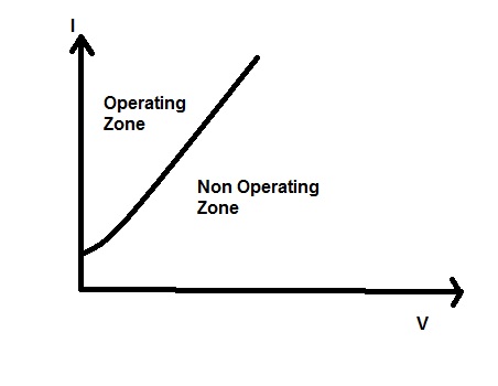
Operating Characteristics on V-I Diagram:
Initial bend in the characteristics is because of the presence of spring torque. For the characteristics it is obvious that 1/slope i.e. 1/tanƟ shall be less than a specified value therefore the Relay will operate in the operating zone and won’t operate in non operating zone as shown in diagram. It shall also be noted that even though voltage fed to Relay is zero but relay is not operating while having current in its operating coil, this is because of presence of Restraining Spring Torque.
Operating Characteristics on R-X Diagram:
The operating characteristic of Impedance Relay is shown below. It is clear from the characteristics that if the impedance seen by the Relay lies within the circle then the Relay shall operate else it won’t operate. For the impedance Z as shown in figure, the current is lagging behind the Voltage by angle Ɵ. If current and voltage were in phase then Z vector would have coincided with the +R axis. If the current leads the voltage then Z vector will be either in third or fourth quadrant. Again in case current lags the voltage by 180 degree then Z vector coincides with –R axis. Here it should be noted that Resistance is not negative rather it implies that current is lagging by 180 degree.

As the operating characteristics of Impedance Relay is a circle in nature, this Relay is non direction i.e. it doesn’t matter whether the current is leading or lagging it will operate if impedance seen by the Relay is within the circle.
But the directional element can be added in cascade with the Impedance Relay to make it directional. This means Impedance Relay will only operate if the directional unit picks up and impedance seen by relay is within the circle. For providing directional feature we need to draw a Zero Torque Line to separate the R-X plane in Operate and Do not Operate region as shown in figure.
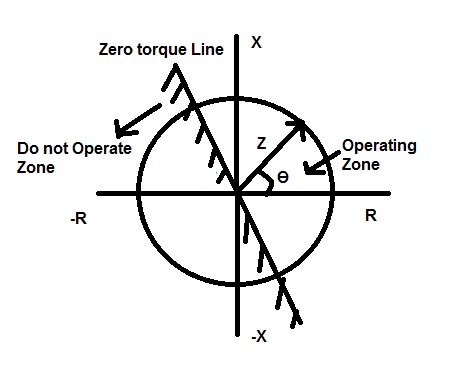
Therefore,if the impedance seen by the Relay lies in between the region of intersection of Zero Torque Line and circle then the Relay will operate otherwise it will not operate. Hence we provided directional feature by cascading directional element in the Impedance Relay.
Thank you!