When the distance between the three phase line conductors are not same i.e. they are not spaced equally from each other then it is said to have unsymmetrical spacing. Unsymmetrical spacing of overhead line conductors give rise to unequal voltage in the individual phases at the receiving end even though the flow of current in each phases are same. This unequal voltage is due to difference in inductance of each phase conductor. Thus it is very important to understand the inductance of 3-phase overhead lines.
Inductance of 3-phase Overhead Lines
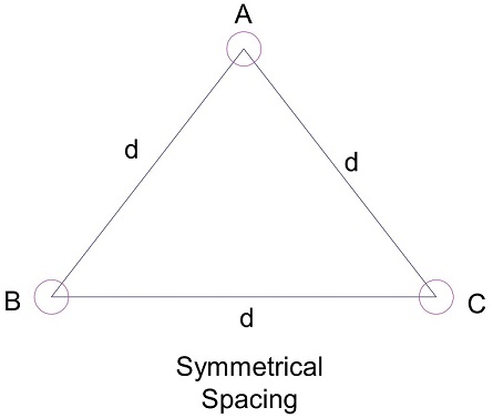
Let us assume that the three conductors each of radius r of 3-phase line are placed along the corners of triangle as shown in figure below. Suppose phase conductors placed at corners A, B and C are carrying current IA, IB and IC respectively. If the load is assumed to be balanced then IA+IB+IC = 0.

Now, we will calculate the inductance of phase conductor placed at corner A. Obviously for that, we need to calculate the total flux linkage of conductor A. If you observe the figure carefully, you will notice that phase conductor placed at corner A will link to the magnetic flux of conductor B and conductor C. Is it? We missed one thing. Phase conductor A will also link to its own magnetic flux. Correct? You will definitely say, YES.
Thus, total flux linkage Ø = Ø1 + Ø2 + Ø3
= (µ0 / 2π)[(0.25-logr)IA – IBlogd1 – IClogd3]
The above equation gives the total flux linkage of phase conductor A. Similarly, the flux linkage of phase conductor B and C can be calculated.
Now we assume that the three conductors are symmetrically spaced as shown in figure below.
The total flux linkage of conductor A
Ø = (µ0 / 2π)[(0.25-logr)IA – IBlogd1 – IClogd3]
But d1 = d2 = d3 = d, hence
Ø = (µ0 / 2π)[(0.25-logr)IA – IBlogd – IClogd]
= (µ0 / 2π)[(0.25-logr)IA – logd(IB + IC)]
But IB + IC = -IA
Ø = (µ0 / 2π)[(0.25-logr)IA + IAlogd]
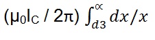
= (µ0IA / 2π)[0.25 + log (d / r)]
Therefore Inductance of Conductor A, LA
= Ø / IA H/m
= (µ0 / 2π)[0.25 + log (d / r)]
As the conductors are symmetrically spaced from each other therefore the flux linkage of each conductor will be same. Due to this, the inductance of each phase conductor will be same. Therefore for symmetrical spacing of 3-phase line conductors,
LA = LB = LC
Effect of Unsymmetrical Spacing of Conductors
The flux linkage of each phase conductors for unsymmetrical spacing are not same. Due to this the inductance of the three phase conductors will be different. Because of this, there will be unequal voltage drop in the three phases even though the currents in phase conductors are balanced. Thus the voltage at the receiving end will not be same for the three phases. To have equal voltage drop in phase conductors, we normally interchange the positions of conductors at equal interval along the line. This interchanging is known as Transposition of line.