What is Freewheling Diode?
A freewheeling diode is basically a diode connected across the inductive load terminals to prevent the development of high voltage across the switch. When the inductive circuit is switched off, this diode gives a short circuit path for the flow of inductor decay current and hence dissipation of stored energy in the inductor. This diode is also called Flywheel or Flyback diode.
Purpose of Freewheeling Diode
The main purpose of freewheeling or flyback diode is to free wheel the stored energy in inductor by providing a short circuit path. This is necessary else a sudden decay in circuit current will give rise to high voltage across the switch contacts and diode.
For better understanding, let us consider the figure below.
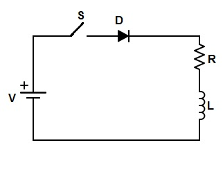
When switch S is closed, the steady state current I through the circuit is (V/R) and hence the stored energy in inductor is (LI2)/2. When this switch S is opened, the current will suddenly decay to zero from steady value I = (V/R). Due to this sudden decay of current, a high reverse voltage (as per lenz’s law) equal to L(di/dt) will appear across the inductor terminals and hence across the diode and switch. This will lead to sparking across the switch contacts. If this reverse voltage exceeds the Peak Inverse Voltage of diode, then it may get damage. To avoid such occurrences, a diode, called freewheeling or flyback diode is connected across the inductive load RL as shown in figure below.
For better understanding of how freewheeling diode prevents such occurrences of over voltages and when it come into play, let us focus on the working principle and circuit diagram of flyback diode.
Working Principle of Freewheeling Diode:
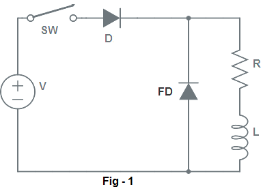
In figure-1, inductive load RL is connected to the DC source through switch SW and diode D. When this switch SW is closed at t = 0 sec, current starts to flow through the load. This current builds up in the inductor and reaches its steady value after some time (roughly 2-3 time constant).
When the switch SW is opened at t = 0 (say), current in the circuit tends to decay through the load. This decay of current through inductor results in development of a reverse voltage equal to L(di/dt) across the inductor terminals. This reverse voltage across inductor terminal makes freewheeling diode forward biased. Thus freewheeling diode behaves like a closed switch as shown in figure below.
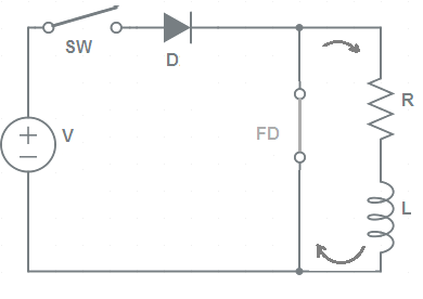
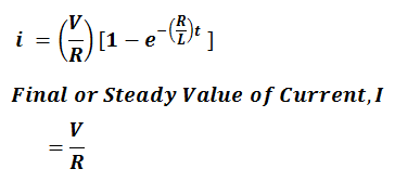
Thus, the main circuit current is transferred to the circuit consisting of freewheeling diode FD, R and L as shown in above figure. In this new circuit, the current will exponentially decay to zero. This decaying current in the circuit is given as below.
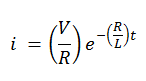
Thus we see that, freewheeling diode dissipates the stored energy in inductor by providing a short circuit path. It also provides a shorted path for exponentially decay of circuit current. Thus high voltage is not induced. Therefore, the switches and diode is protected from the high voltage.
Hello,
Thank you for the explanation there are yet some things that I don’t understand.
– After that the inductor is loaded and switch is switched back open, why does the current go through the freewheele diode and not back through the source supply? I don’t understand why the current can’t just flow back into the original source.
– Doesn’t the currect go through the inductor back to the resistor and in reverse through the diode? the polarity has changed when opening the switch.
These 2 things I can not find explanation for on google.
Thank you in advance!
Thank you for asking. Point wise explanation:
1) Since switch is open, the path for flow of current through source is open. Hence the current can’t flow through the inductor and back to source.
2) No the current can’t go through Diode as the switch is open so the circuit is open. The current flows flows through the freewheeling diode, resistor and inductor when switch is opened. This is due to induced emf in the inductor which has opposite polarity as per lenz law. This will make free wheeling diode forward biased, hence it works like a shorted path. Current always flows through less resistive path. As tit is shorted, the entire discharge current of inductor will flow through FD, Resistance R and Inductor.
Did you understand? Please let me know if you need more clarification.
The explanation is to the point and clear…thanks for clearing all my doubts. I’m studying for gate 2020. Please guide me as to how to study electrical services subject. I’m planning on studying the whole syllabus from your website…it has amazing content.
Thank you!
Explenation was quite intersting which text are you refering?
Or r u a research scholar.?
can you please show a psim of freewheeling diode
Please can someone help me how to solve integrated circuit
Can we use this freewheeling diode across DC Motor terminals.
We are observing spikes in vibration sensor when a near by DC Motor is switched on
can the circuit protect the no nc contacts of 24vdc relay that can be used to drive hydraulic cylinder value taken signal from plc through relays