Peak Inverse Voltage or PIV is the maximum voltage appearing across the p-n junction diode when it is non-conducting. A diode do not conducts when it is reversed biased. This means peak inverse voltage is the maximum reversed biased voltage across the diode terminals when it is put in a circuit.
Every diode has a specified value of PIV as mentioned in the datasheet provided by the manufacturer. In no case the reversed biased voltage should exceed this PIV else it may lead to damage of diode. Generally the maximum rated peak inverse voltage (PIV) of silicon diode is more than that of Germanium diode.
Let us now discuss and find the value of PIV in half wave rectifier, Center tapped full wave rectifier and bridge rectifier one by one.
Peak Inverse Voltage in Half Wave Rectifier
To get an idea of PIV, we should focus the voltage appearing across the diode terminals when it is non-conduction i.e. reversed biased. So for this case, diode may be replaced by an open switch as shown below.
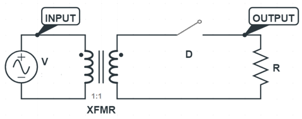
It can be seen from the above circuit diagram that the voltage appearing across the diode terminal during reversed biased condition is equal to VmSinωt i.e. negative half cycle of the sinusoidal AC supply voltage. Since the peak value of the sinusoidal AC supply is Vm, therefore the maximum reversed biased voltage across the diode is also equal to Vm. Therefore, the peak inverse voltage of diode in half wave rectifier is equal to the peak value of the supply voltage.
Peak Inverse Voltage in Center Tapped Full Wave Rectifier
First of all we should replace the diode by an open switch to simulate reversed biased condition to get the PIV of diode.
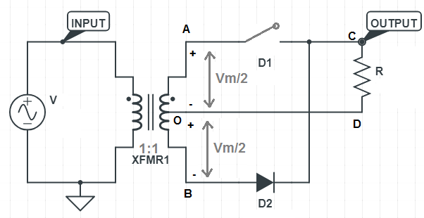
Note that we have replaced diode D1 by an open switch to simulate its reversed biased condition during the negative half cycle of the supply voltage. You can also replace D2 by an open switch as it is non-conducting during the positive half cycle of supply.
You may think, since diode D1 is connected in between the center tap and one secondary terminal, the voltage appearing across this diode terminal during negative half cycle of supply voltage will be equal to half of the voltage appearing across the secondary terminals of transformer. But it must also be noted that, D1 is connected to the source through D2 and ‘A’ point as diode D2 is conducting. Therefore the voltage across diode D1 will not be equal to the voltage between center tap and xecondary terminal A rather it will be equal to full supply voltage. Therefore the maximum voltage to which D1 is subjected during its reversed biased condition is equal to the peak value of supply voltage i.e. Vm. As turn ratio of transformer is assumed to be 1:1, therefore the voltage in between center tap and one secondary terminal i.e. A & O will be (VmSinωt)/2. Therefore the peak inverse voltage of diode in center tapped full wave rectifier is twice the secondary terminal voltage of transformer.
Peak Inverse Voltage in Bridge Rectifier
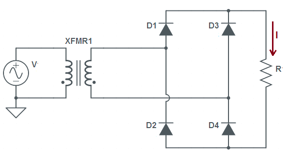
Figure below shows the circuit diagram of full wave bridge rectifier.
Let us proceed in the same way as in half wave and center tapped full wave rectifier. So consider the circuit below.
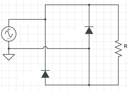
In the above figure, the two diodes are shorted. Since during positive half cycle of supply voltage, the two diagonally opposite diodes conducts therefore they are shorted. Now you can easily see that the voltage across each of the reaming two diodes is equal to supply voltage and they are reversed biased. Therefore the maximum reversed biased voltage across each of the non-conducting diode is equal to the peak value of supply voltage. Hence, the peak inverse voltage of diode in bridge rectifier is equal to the peak value of supply voltage.
Thus the peak inverse voltage of diode in half wave, center tapped full wave and bridge rectifier are Vm, Vm and Vm respectively where Vm is the peak value of supply voltage.
good concept
Thank you!
You should also consider when there is a holding electrolytic capacitor at the bridge output with light or no load fully charged to VAC – RMS, that voltage will add up to the peach AC input voltage when calculating the diode’s PIV.