Definition:
Hall Effect Transducer is a device which is used for the measurement of magnetic field strength. This transducer uses a conducting strip to convert magnetic field into proportional potential difference across the opposite faces of strip using Hall Effect.
Working Principle:
The working principle of Hall Effect Transducer is based on Hall Effect. Hall Effect is basically the process of development of potential difference across the two faces of a current carrying strip when the strip is kept in a magnetic field. The magnitude of voltage depends upon the current, strength of magnetic field and the property of conducting material. The Hall Effect is found in conducting material and semiconductor in varying amount depending upon the density and mobility of current carrier.
Let us consider the figure below. This figure explains the working principle of hall effect transducer.
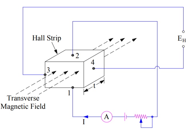
In the above figure a conducting strip is kept in a transverse magnetic field. Note that the current through the strip and the magnetic field are perpendicular to each other. Flow of current means the flow of positive charges in the direction of current. This means that, magnetic field will exert a force on the moving positive charges as per F = q(vXB) where v & B are the velocity and strength of magnetic field. v & B are in vector form.
Since v and B are perpendicular to each other, the magnitude of force on the moving positive charges will be
F = qvB
The direction of force F will be perpendicular to both the v and B as per the law of cross product of two vectors. This essentially means that F will be directed from edge 3 to 4 in the above figure.
Due to this force on the positive charges, these charges will continue to accumulate on the face 3 which in turn will create an Electric Field. The direction of electric filed will be opposite to the direction of F i.e. from edge 3 to 4. Therefore, after some time, the magnitude of force exerted by electric filed E and F will become equal and hence there will not be any further movement of the charges.
qE = F (qE is the force on the positive charge due to electric filed)
qE = qvB
E = vB
Due to set-up of electric filed E in the conducting strip across edge 3 and 4, a potential difference will be produced across this face. Assuming the thickness of strip to be “t”, the strength of potential difference across 3 & 4 is given as
EH = Et
= vBt …….(1)
Since the current density through a material is directly proportional to the velocity of carriers, therefore
v = KHJ ……..(2)
where J is the current through the strip and KH is a constant of proportionality called the Hall Effect Coefficient. But J = I/A where A is the surface area, therefore,
J = I/t2
Hence, from information (2),
v = KHI / t2
From information (1),
EH = (KHIB) / t ……..(3)
The above expression gives the voltage developed due to Hall Effect. This voltage is called the hall effect emf and used to either measure the magnitude of current or magnetic field strength.
The magnitude of Hall Effect emf is very small in conductors and hence very difficult to measure. However, its value if quite sufficient in semiconductors and can easily be measured by sensitive moving coil instruments.
Application of Hall Effect Transducer:
The major applications of Hall Effect Transducer are described below:
Measurement of Magnetic Field Strength:
The Hall Effect Transducer can be used as a Magnetic to Electric Transducer. This means that this transducer can be used to measure the magnetic field. To measure the magnetic field strength, a semiconducting plate is inserted perpendicular to the magnetic field. The transducer gives an output voltage proportional to B, the magnetic flux density.
The advantage of this transducer to measure magnetic field is that it requires less space however, the major disadvantage is that such type of transducer is very sensitive to temperature changes. Further, different material produced different hall effect emf and hence calibration of individual transducer is required if different materials are used.
Measurement of Displacement:
The hall effect element is used for the measurement of the location or displacement of a structural element i.e. it serves as an indirect acting position displacement or proximity transducer in case where a change in geometry magnetic structure causes a change in the magnetic field strength. Figure below shows a ferro-magnetic structure having a permanent magnet. The hall effect transducer is placed in the gap adjacent to the permanent magnet.
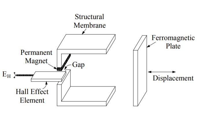
The filed strength produced by the permanent magnet changes as the position of the ferro-magnetic structure is varied. Due to change in magnetic field strength, the hall effect emf changes which can be calibrated with the displacement of ferro-magnetic plate. In this way, it works as a sensor to sense the displacement / position of the plate.
Measurement of Current:
Hall Effect Transducer is a great way to measure the current flowing in a circuit without actually interrupting the circuit. In this application, actual connection between the circuit whose current is to be measured and the metering instrument is not required. What we need is to just surround the circuit element by a ferro-magnetic tube and insert a hall effect element in the slot of the ferro-magnetic tube. This ferro-magnetic tube is called magnetic concentrator as its purpose is to concentrate the magnetic field created by the current carrying circuit element. Figure below depicts a typical current measuring application of hall effect transducer.
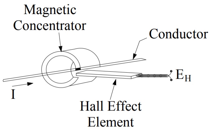
In the above figure, the conductor is carrying current (it may be AC or DC). This current creates a magnetic field around it. The value of this magnetic field is proportional to the current and given by Biot Savart Law. When a Hall Effect element is kept perpendicular to the magnetic field in the slot of ferro-magnetic concentrator, a hall effect emf is produced and given by (3). The magnitude of emf is proportional to current flowing in the conductor (as the magnetic field B created by current carrying circuit element is proportional to the value of current flowing through it). Thus, the measured emf across the hall effect transducer gives the magnitude of current flowing through the circuit.
Hall effect transducer can measure the current from few mili ampere (mA) to thousands of ampere (A). If the value of current to be measured is less then ferro-magnetic concentrator is required. However, where the magnitude of current to be measured is large, magnetic concentrator may be omitted as the magnetic field created by large current will be sufficient enough to have significant value of hall effect emf.
Hall Effect Transducer is also used for measurement of power.
How would you use a hall effect sensor to read a recording made on a wire recorder, cassette or reel to reel recorder?
Bob H
Transducers play a vital role in converting physical signals into measurable electrical outputs. This makes them essential in industries like healthcare, engineering, and automation. Explore cutting-edge services and products atc/ or contact us at +91 80 3542 9949 for collaboration and innovation opportunities. Elevate your projects with Proact’s expertise.