Current Commutated Chopper is a type of chopper in which commutation of thyristor used in the circuit take place due to oscillatory current through it. This article explains current commutated chopper along with its circuit diagram, working principle and various waveforms.
Circuit Diagram:
The circuit diagram of a current commutated chopper is shown below. In this diagram, T1 is the main thyristor. The commutation circuitry comprises of TA (the auxiliary thyristor), Capacitor C, Inductor L and Diode D1 & D2.
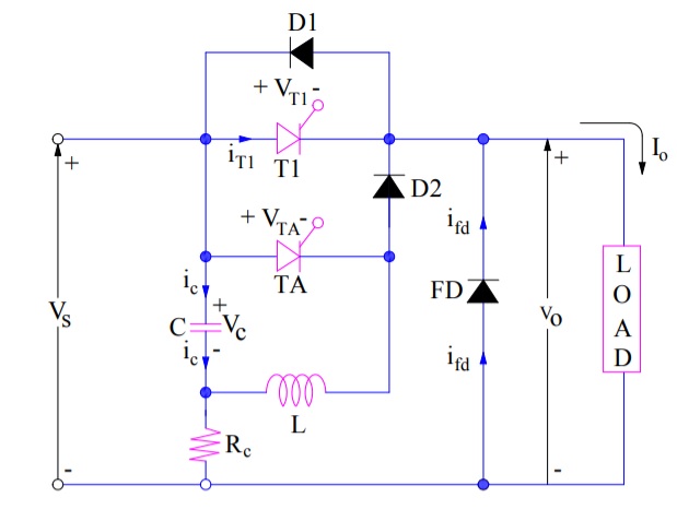
FD is the free-wheeling diode and RC is the charging resistor. To make the analysis simple, following assumptions are made:
- Load current is constant
- SCRs and diodes are ideal switch
- Charging Resistor RC is very large and can be treated as open circuit during commutation.
- Current ic, iT1, ifd and io are treated as positive when these are in the arrow directions marked. Similarly, voltages vc, vT1, vTA and vo are taken positive with the polarities as marked in the circuit diagram.
Working Principle of Current Commutated Chopper:
The working principle of current commutated chopper is based on current commutation technique of thyristor. The energy required for commutation comes from the charged capacitor C. This capacitor is first charged to source voltage Vs by charging resistor RC. Once the capacitor C is charged to Vs, main thyristor T1 is turned ON so that load voltage vo becomes equal to source voltage Vs and load current io = Io. With the turning ON of T1, the commutation circuitry remains inactive. It comes into service when the auxiliary thyristor TA is fired.
The working principle of current commutated chopper can be divided into five modes just to have better understanding.
Mode-1:
At time t = 0, main SCR T1 is fired which results in load voltage and current to be equal to Vs and Io respectively. This is because, the load is directly connected to source through T1. The equivalent circuit diagram for Mode-1 is shown below.

To start commutation of main thyristor T1, auxiliary thyristor TA is turned ON (say at t=t1). This results in an oscillatory circuit comprising of C, L and TA. The voltage and current through this oscillatory circuit vary sinusoidally.
The magnitude of oscillatory current is given as

During the time interval (t2-t1), ic and vc vary sinusoidally through half a cycle (Refer waveform section). In this mode, the current through the oscillatory circuit is maximum when the voltage across the capacitor reduces to zero. At t2, the current through the oscillatory circuit tend to reverse in the auxiliary thyristor TA and hence, it gets naturally commutated. At t2, vc = -Vs as shown in the waveform. This means, the lower plate of capacitor is positively charged while the upper plate is negatively charged. Note that, T1 remains unaffected during this mode and hence load current and voltage will remain to be Io & Vo respectively.
Mode-2:
As TA is turned off at t2, oscillatory current begins to flow through C, L, D2 and T1. Refer the equivalent circuit diagram for this mode shown below.

It should be noted that the current will flow through T1 not through D1. This is because the D1 is reversed biased by a small voltage drop across the conducting thyristor T1. Therefore, after t2, ic would pass through T1 not through D1.
In thyristor T1, ic is in opposition to the load current io so that iT1 = (Io – ic). At some time t3 when ic rises to Io, the current through the main thyristor will reduce to zero and hence it will be commutated i.e. turned off at t = t3. Since the oscillatory current through T1 turns it off, it is called current commutated chopper.
During this mode, load voltage remains Vs through T1. For this mode, t2<t<t3.
Mode-3:
As T1 is turned off at t=t3, ic becomes more that Io. After t3, ic supplies load current Io and the excess current (ic – Io) is conducted through D1. This mode of operation is depicted in the figure below.

The voltage drop in D1 keeps T1 reversed biased for (t4-t3) = tc; this is shown in the waveform of vT1. At t4, if vc becomes more than Vs, FD comes into conduction otherwise Mode-4 would follow. During Mode-3, when ic is at its peak value, voltage across capacitor becomes equal to zero. After this peak, capacitor voltage reverses and its upper and lower plate becomes positive & negative respectively.
Mode-4:
At t = t4, capacitor current ic reduces to zero. This results in iD1 = 0 and diode D1 is turned off. After t4, a constant load current Io begins to flow through capacitor C, L and D2. Since current through capacitor is constant, it begins to charge linearly till voltage across it becomes equal to source voltage Vs. Note that, current is constant (equal to Io) during this period i.e. (t5-t4).
The equivalent circuit diagram for Mode-4 operation of current commutated chopper is shown below.

As D1 is turned off at t4, vT1 = vTA = vc; this is shown as ab in the waveform for vc, vT1 and vTA. Now the load voltage vo = Vs – vc = Vs – voltage ab at t4. At t5, vc = Vs, therefore load voltage reduces to zero at this moment. During the time interval (t5-t4), vc increases linearly, therefore load voltage vo decreases linearly to zero during this time interval.
Mode-5:
At t5, the capacitor is actually overcharged to a voltage somewhat more than the source voltage Vs. Therefore, free-wheeling diode FD gets forward biased and starts to conduct the load current Io at t5. Load voltage reduces to zero at t5 as discussed in Mode-4. Mode-5 operation of current commutated chopper is shown below.

As ic is not zero at t5, the capacitor C is still connected to the load through Vs, C, L and D2. As a consequence, C is overcharged by the transfer of energy from L to C. At t6, capacitor current becomes zero and the voltage across it becomes more than the source voltage.
During (t6-t5), capacitor current and current through free-wheeling diode feeds the load i.e. ic+ifd = Io. From t5 onwards, io freewheels through FD. As ic is zero and D2 is open circuited, C now discharges through RC for the freewheeling interval of chopper. After t5, vT1 remains constant at Vs, because Vs reaches T1 terminal through FD. AT t=T, the main SCR is again triggered and the Mode-1 to Mode-5 is repeated again.
Waveforms of Current Commutated Chopper:
Various waveforms for current commutated chopper are shown below.

Advantages of Current Commutated Chopper:
Following are the advantages of current commutated chopper:
- Commutation is reliable so long as the load current is less than the peak commutating current.
- Capacitor is always charged with correct polarity.
- Auxiliary thyristor is naturally commutated as its commutating current passes through zero value in the oscillatory circuit formed by L & C.