Most of us use laptop / mobile and we charge our laptop daily by using their charger. But did you ever notice the round portion on the charger as shown in figure below.
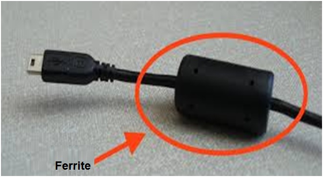
Did you ever think of what is that round portion? The round portion as shown in the figure is Ferrite used for the suppression of interference. In this post we will discuss how Ferrite helps to reduce the interference.
As we know, current flowing through a conductor creates a magnetic field around it. Transfer of energy between the current and the magnetic field is affected through the inductance of the conductor. For a straight wire the self-inductance is typically 20nH per inch. Placing a magnetically permeable material around the conductor increases the flux density for a given field strength and therefore increases the inductance.
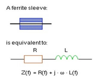
Ferrite is a magnetically permeable material whose permeability is dependent on frequency. Also the permeability is complex and has both real and imaginary parts i.e. inductive and resistive components. The ratio of these components varies with frequency – at the higher frequencies the resistive part dominates (the ferrite can be viewed as a frequency dependent resistor) and the assembly becomes lossy.
Figure below shows the Ferrite sleeve and its equivalent circuit.
Where to use Ferrite Sleeve?
Cables normally carry signal and return, and / or power and return, conductor pairs. Multiway cables may carry several such pairs. The magnetic field produced by the intended “go” current in each circuit pair is cancelled by the field produced by its equal and opposite “return” current, provided that the two conductors are adjacent. This is known as Differential Mode. Placing a ferrite around a cable, then, has no effect on the differential mode signals carried within the cable.
A cable carries currents in common mode, that is, all conductors have current flowing in the same direction. Normally, this is an unintended by-product of the cable connection, and the current amplitudes are small, not more than a few microamps. The source of such currents is usually either
- Ground-referred noise at the point of connection, which may have nothing to do with the signal carried on the cables, or
- Imbalance of the impedance to ground of the various signal and return circuits, so that part of the signal current returns through paths other than the cable harness.
Since common mode currents on a cable do generate a net magnetic field around the cable, a ferrite inserted around the cable will increase the cable’s local impedance to these currents and hence will suppress this interference.
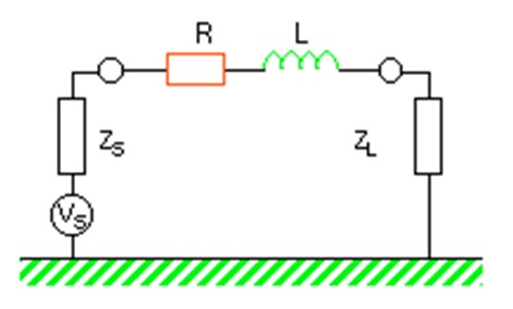
When a ferrite is placed in circuit it operates between source and load impedances. From the equivalent circuit shown in figure above it is clear that maximum attenuation due to the simple impedance divider will occur when ZSand ZL are low.
For example, if ZSand ZL are 10 ohms and the ferrite impedance at a given frequency is 100 ohms,
The total attenuation (with and without ferrite) is
A = 20log10 [(10+10)/(10+100+10)] = -15.6dB
but if the circuit impedance is 200 ohms, the attenuation becomes
A = 20log10 [(200+200)/(200+100+200)] = -2dB
Thus it is clear that attenuation of noise signal will be more if the siurce and load impedance is low when compared with Ferrite impedance.
Thank you!