Maxwell Bridge is used for the measurement of Self-Inductance. Like other bridge, this method also works on balancing of bridge. Balancing of bridge is achieved when there is no current through the detector. Don’t worry we will be discussing everything in detail in this post.
Maxwell’s Bridge employs the comparison of test specimen variable standard inductor for the measurement of inductance. Basically there are two different bridges in Maxwell’s Brdige, one is Maxwell Inductance Bridge and second one is Maxwell Inductance-Capacitance Bridge.
Maxwell Inductance Bridge:
The connection diagram and the phasor drawing of Maxwell Inductance Bridge is shown in figure below.
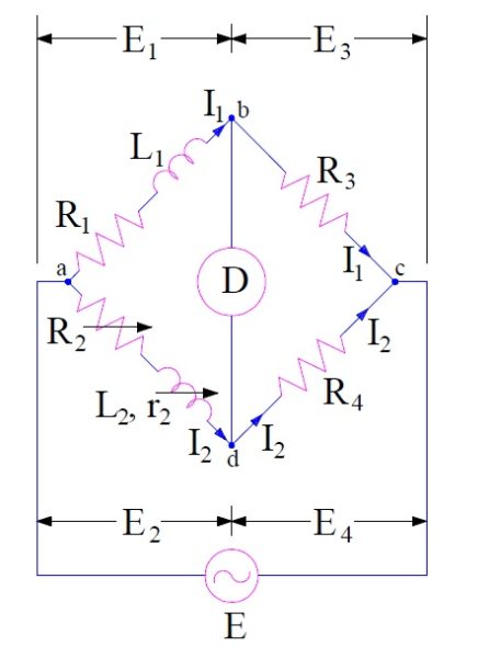
In the above circuit,
L1 = Unknown inductance having resistance R1
L2 = Variable standard inductance with fixed resistance r2
R2 = Variable resistance
R3 and R4 = Known resistance
As we know that, for a balanced bridge the multiplication of impedances of opposite arms must be equal.
Impedance of arm ab, Z1 = (R1+jwL1)
Impedance of arm cd, Z2 = R4
Impedance of arm ad, Z3 = (R2+r2+jwL2)
Impedance of arm bc, Z4 = R3
Hence for balanced bridge,
Z1Z2 =Z3Z4
(R1+jwL1)xR4 = (R2+r2+jwL2)xR3
R1R4-R2R3-r2R3+jw(L1R4-L2R3) = 0
Equating real and imaginary part we get,
R1R4-R2R3-r2R3 = 0 ……………(1)
and (L1R4-L2R3) = 0 ……………(2)
From (1),
R1R4 = R2R3+r2R3
= R3(R2+r2)
Hence, R1 = (R3/R4)(R2+r2)
Now from (2),
L1R4 = L2R3
Hence, L1 = L2R3 / R4
Thus unknown inductance L1 and its resistance R1 may be calculated.
Phasor diagram of Maxwell Inductance Bridge is shown below.

Maxwell Inductance Capacitance Bridge:
In this method, the unknown inductance is measured by comparison with standard known capacitance. The connection diagram of Maxwell Inductance Capacitance Bridge is shown below.
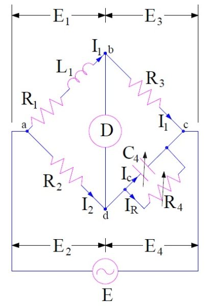
In the above diagram,
L1 = Unknown inductance with resistance R1
C4 =variable standard capacitor
R2, R3 & R4 = Known fixed resistance
Now,
Impedance of arm ab, Z1 = (R1+jwL1)
Impedance of arm cd, Z2 = R4 / (1+jwC4R4)
Impedance of arm ad, Z3 = R2
Impedance of arm bc, Z4 = R3
For bridge to be balance,
Z1Z2 =Z3Z4
(R1+jwL1)x [R4 / (1+jwC4R4)] = R2R3
R1R4-R2R3 +jw(L1R4-R2R3C4R4) = 0
Equating real and imaginary parts we get,
R1 = R2R3 / R4
and L1 = R2R3C4
The quality factor of inductor may also be calculated as
Q = wL1/R1
= wR2R3C4 / R1
Since R4 = R2R3C4 / R1 , hence
Q = wC4R4
The phasor diagram of Maxwell Inductance Capacitance Bridge is shown below.

Advantage:
- The expression of inductance is independent of frequency.
- A wide range of inductance can be measured at power and audio frequencies.
- The expression for inductance is simple and can easily be calculated.
Disadvantage:
Since Maxwell Inductance Capacitance Bridge uses variable standard capacitor, it is very expensive to get variable standard capacitor.
Applicability of Maxwell Bridge:
Maxwell Bridge is suitable for the measurement of inductance with medium vale of Q (1<Q<10). This method is not suitable for measurement of inductance with high value of quality factor Q. Since Q = wC4R4, we will need higher value of resistance R4 for measurement of high Q coil which is very expensive.