Before going into the phasor diagram of transformer, there are some important points which must be kept in mind. Based on these points, we will draw the phasor diagram for No Load, Lagging Load and Leading Load condition of transformer.
Important Points for Phasor Diagram of Transformer:
1) Transformer when excited at no load, only takes excitation current which leads the working Flux by Hysteretic angle α.
2) Excitation current is made up of two components, one in phase with the applied Voltage V is called Core Loss component (Ic) and another in phase with the working Flux Ø called Magnetizing Current (Im).
3) Electromotive Force (EMF) created by working Flux Ø lags behind it by 90 degree.
4) When Transformer is connected with a Load, it takes extra current I’ from the Source so that N1I’ = N2I2 where I’ is called load component of Primary Current I.
So under load condition, I1 = Primary Current, is phasor Sum of I’ and Excitation Current Ie.
Phasor Diagram for No Load Condition:
Transformer at no load means that its secondary winding is open and primary is energized from voltage source. Figure below shows this condition.
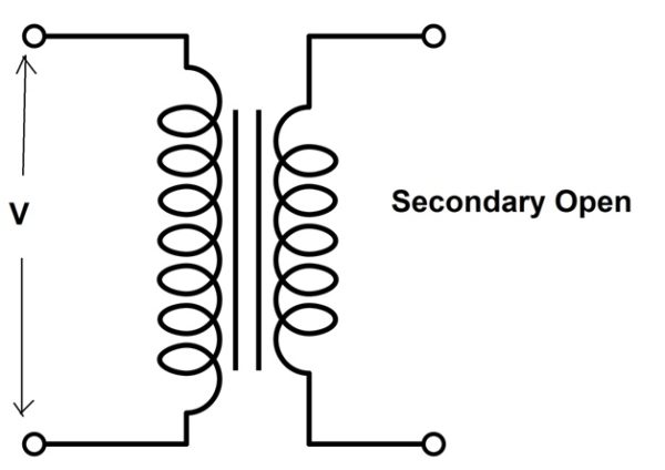
Following steps should be followed for phasor diagram of transformer at no load condition:
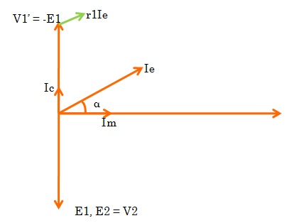
- Working Flux Ø taken as Reference as shown below.

- Excitation Current Ie leading Ø by α.

- Induced EMF E1 and E2 lagging Flux by 90 degree.

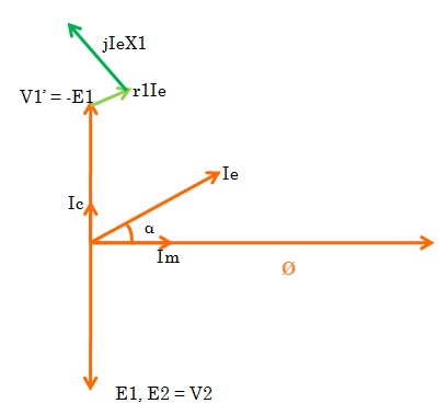
- Voltage drop r1Ie in Primary. This will be in phase with the Ie and hence shown parallel to it in the figure below.
- Voltage drop IeX1 in Primary due to reactance. This will be perpendicular to Ie as shown below. (Why perpendicular to Ie? Please write in comment box.)
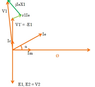
- Source Voltage V1 = V1’+r1Ie +jIeX1, phasor sum. Thus the complete phasor diagram of transformer at no load will be as shown below.
Phasor Diagram of Transformer for Lagging Load:
When the transformer secondary is connected to an inductive load, the current flowing in the secondary winding is lagging w.r.t secondary terminal voltage. Let us assume that the current is lagging by an angle of ɵ2.

Let, r1 = Primary winding Resistance
X1 = Primary winding leakage Reactance
r2 = Secondary winding Resistance
X2 = Secondary winding leakage Reactance
The steps for phasor drawing will be as follows:
If we take the working flux Ø as reference, the phasor diagram of transformer will be as shown below.

I will suggest you to download the ppt or pdf file which covers step by step phasor diagram of transformer for no load, lagging load and leading load condition. Download the file…TRANSFORMER PHASOR DIAGRAM
Excellent