Pole changing method is a speed control scheme of induction motor. In this scheme, the number of pole pairs is changed by changing the field connection. In induction motor, field winding is wound on the stator while the armature winding is wound on the rotor. Therefore in this scheme, provision for changing the stator winding connection is provided to achieve different number of pole pairs.
When the stator winding is energized by three phase AC source, a rotating magnetic flux is developed in the air gap. This magnetic field rotates with synchronous speed. The synchronous speed is given as
Ns = (120f / P) rpm
where f is supply frequency and P is number of pole pairs.
Thus if it is possible to change the value of P, the synchronous speed can be varied.
For a slip s, the rotor speed of induction motor = Ns (1-s)
Therefore speed of induction motor can be varied by pole changing. Since the number of pole pairs can only be changed in steps like from 2 to 4, this scheme provides stepped speed control. Generally, speed control using pole changing method is restricted to two steps.
Basic Principle of Pole Changing Method:
To better understand the basic concept of pole changing; let us consider a magnetic circuit as shown below.
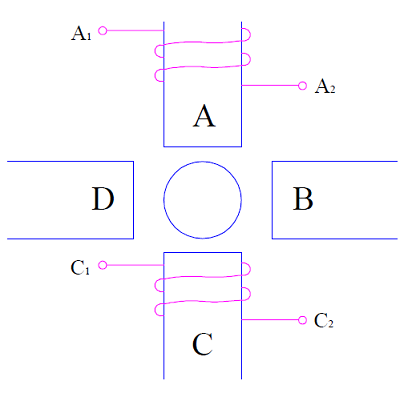
There are four pole faces A, B, C and D. Two coils are wound on pole face A and C in the direction as shown in above figure. Now, the two coils on A and C can be connected in series in two different ways:
Connection-1: Connect coil terminal A2 and C1 together.
In this connection, when supply is connected across coil terminals A1 and C2, the current will flow in the direction as shown in figure.
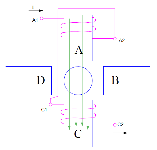
A careful observation of the above figure will reveal that current in both the coils are flowing in clockwise direction. Therefore, the magnetic field due to pole A coil will be emanating from pole. Likewise, the magnetic field due to pole C coil will be going into the coil when viewed from rotor. This is shown in figure by green colored arrow.
As per convention, the pole where from magnetic field emanates is called North Pole and where they enter is called South Pole. Thus pole A is North Pole whereas pole C is South Pole. Thus, this type of connection results into a two pole induction motor. The speed of this induction motor will be
Nr = (120f / P)(1-s)
= (120f /2)(1-s)
= 60f(1-s)
Assuming supply frequency of 50 Hz and slip s = 0.1,
Nr = 3000 (1-0.1)
= 2700 rpm
Connection-2: Connect coil terminal A2 and C2 together.
This connection is known as constant-torque connection. In this connection, the direction of current in pole A coil is clockwise while that in pole C coil is anti-clockwise. This is shown in figure below.
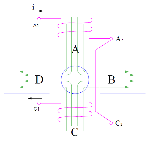
Therefore, the magnetic field due to both the coils will emanate from the respective coil. These magnetic flux lines will complete its circuit through the adjacent pole B and D as shown by green colored lines in the figure.
Thus, this connection of stator coils results into a four pole induction motor whose speed of rotation is given as,
Nr = (120f / P)(1-s)
= (120f /4)(1-s)
= 30f(1-s)
Assuming supply frequency of 50 Hz and slip s = 0.1,
Nr = 1500 (1-0.1)
= 1350 rpm
It is thus clear from the above discussion that speed control of induction motor using pole changing method is achieved in steps. We cannot have a continuous or smooth speed control using this method.
It is also worth to note that; supply voltage drop is taking place in the series connection of the two coils. Hence, the magnetic flux in the air gap will remain constant. This in turn means that induction motor torque will be constant. This is the reason; this kind of stator winding connection is called constant-torque connection.
Apart from the above two types of connection, let us also consider a different type of connection known as constant horse power connection.
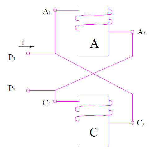
It is clear from the above figure that; this connection will result in a four pole induction motor. Since both coils are connected in parallel, the supply voltage will drop only across single coil. Therefore the flux in the air gap will be halved as compare to constant horse power connection. But the power will remain constant. That is why, it is called constant horse power connection.