A tap changer designed to operate while the Transformer is charged is called On Load Tap Changer (OLTC). On Load Tap Changer, OLTC is Make Before Break type which ensures that no sparking will take place while operating OLTC. On Load Tap Changer (OLTC) is used for short period or daily voltage regulation. During the operation of On Load Tap Changer, OLTC following two things shall be taken care:
- The main circuit shall not be opened else heavy sparking will take place.
- No part of tapped winding shall be shorted.
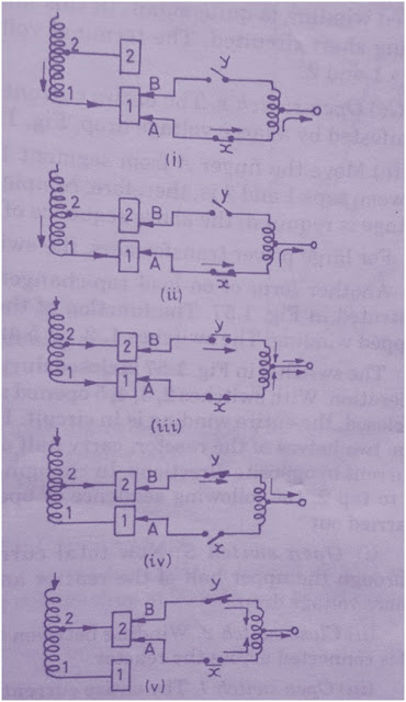
The above figure shows the elementary form of On Load tap Changer, OLTC. As shown in the figure the center tapped Reactor C prevents the tapped winding from getting short circuited. The Transformer tappings are connected to the segments 1 to 5. Two fingers A and B are movable and connected with the Centre Tapped Reactor through switches x and y and make contact with any one of the segment 1 to 5 under normal operation.
As clear from the figure, both the fingers A and B are connected with segment 1 and switches x and y are closed, thereby whole winding is in circuit. As both the fingers are connected with the segment 1, half of the current will flow from the lower part of the Center tapped Reactor C and half of the current will flow from upper part. As the Reactor is wound in the same direction, therefore mmf because of upper half of the current and lower half of the current will cancel out in Reactor. Therefore Reactor will be behave like non inductive and will not offer any impedance. Therefore, the voltage drop in the center tapped Reactor will be very small.
Now to change the tapping of the Transformer, following sequence of operation will take place one by one. The steps to be taken for changing the tap are shown in figure below.
Step1: Open Switch y
The entire current now will flow through switch x and lower half of the Reactor C. It therefore becomes highly inductive and there will be a large voltage drop across it. Reactor C shall be designed to withstand full load current momentarily.
Step2: Move Finger B
As the Switch y is open therefore finger B is not carrying any current and can be moved to segment 2 without any sparking.
Step3: Close Switch y
Now close Switch y. Now the Transformer winding between tap 1 and 2 get connected through the Reactor C. As the impedance offered by the Reactor is high for current flowing only in one direction, the circulating current through the Reactor, finger A and finger B will be very less. In this manner the Reactor prevents the tapped winding from getting short circuited.
Step4: Open Switch x
Now the entire current will flow from the upper half portion of the Reactor causing a high voltage drop across it.
Step5: Move Finger A
As the Switch x is open therefore finger A is not carrying any current and can be moved to segment 2 without any sparking.
In this way, the winding between segment 1 and 2 is completely cut out. If further change in voltage is required, above sequence of operation is repeated.


helpfull
What kind of switches are these( X and Y) practically? …as they have to interrupt almost half of nominal load current
easy to understand , explanation regarding function of oltc is with clarity