The main purpose of compensating winding is to nullify the effect of armature reaction on the main field flux under the pole faces in DC machine. Due to the effect of armature reaction mmf, the flux distribution under the pole faces is distorted which leads to poor commutation and flashover.
When a DC machine is operated at heavy load or operated with a weak main field, the effect of armature reaction flux dominates. Due to this the resultant air gap flux gets heavily distorted. In the interpolar region, the effect of armature reaction is neutralized by the interpole winding but the distortion prevails under the pole face as shown in the figure below.
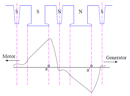
Any coil whose two coil sides are under the influence of this distorted peak flux will have a large rotational emf (Bvl) induced in it. In the above figure, the coil sides a and a’ are shown under the peak flux. If the rotational emf in the coil sides a and a’ exceeds the limit i.e. 30 to 40 V, the air in between the adjacent commutator segment to which the coil aa’ is connected may breakdown. This breakdown will result in an arc which may eventually spread to the nearby commutator segment. Such kind of flashover is detrimental for commutator surface as well as supply line as the supply line is directly shorted by the arc.
The trouble of flashover due to the distortion of flux density wave under the pole shoe is overcome by the use of compensating winding. Compensating winding basically nullifies the effect of armature reaction under the pole shoe.
Compensating winding is also known as pole face winding. This winding is embedded in the slots in pole faces. It is connected in series with the armature winding so that their mmfs are proportional to the same current. To compensate the effect of armature reaction, the direction of current in compensating winding must be opposite to that in the armature winding just below the pole face as shown in figure below.

Half of the compensating winding in the right side pole face is connected in series with the half of the left side pole face winding as shown in above figure. In this way, the direction of current in compensating winding is opposite to that in the armature winding.
Figure below illustrate how the compensating winding mmf neutralizes the armature mmf under the pole face.
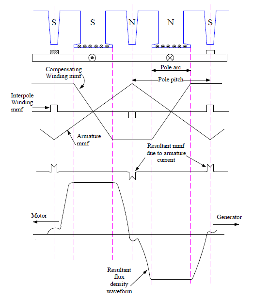
In the interpolar region, both the interpole winding and compensating winding opposes the armature mmf. Under the pole face, the armature mmf is neutralized by the compensating winding mmf. Therefore the resultant air gap flux becomes independent of the load current and rectangular in shape.