Zero Power Factor Characteristics
Zero Power Factor Characteristics (zpfc) of synchronous generator is a plot between the armature terminal voltage and field current for a constant value of armature current and speed. A purely inductive load is connected across the generator terminal to achieve zero power factor and zpfc.
Zero power factor characteristics along with Open Circuit Characteristics of generator are used to evaluate the value of armature leakage reactance xal and armature reaction mmf Fa. zpfc for a synchronous generator is obtained as follows:
- The synchronous machine is operated at synchronous speed by the prime mover.
- A purely inductive load is connected at the generator terminal and field current is increased till rated current starts flowing in the armature winding.
- The load is varied in steps and field current is also adjusted so that rated current flow in the armature. In each step, the armature terminal voltage and field current is measured and noted. A plot between these two noted quantities is drawn. This plot is the zero power factor characteristics of generator.
A typical zpfc is shown in figure below. The figure below also includes the phasor diagram of synchronous generator under the condition of zero power factor.
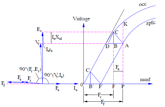
From the above phasor diagram, it can be easily seen that terminal voltage Vt and air gap voltage Er are almost in phase. Since the armature resistance is negligible as compared to leakage reactance xal, therefore
Vt = Er − Iaxal
The filed mmf Ff and resultant air gap mmf Fr is also almost in phase, therefore
Ff = Fr + Fa
Potier Triangle
Potier Triangle is a right angled triangle whose perpendicular and base represents the voltage drop in armature leakage reactance (Iaxal) and armature mmf Fa respectively. This triangle is used to draw the zero power factor characteristics (zpfc) from the open circuit characteristics (OCC) of synchronous generator.
In the above figure OCC and zpfc are shown. For field excitation Ff, the armature terminal voltage is ‘PK’ under open circuit condition. Keeping filed current If and speed constant, when the generator armature is connected with purely inductive load, the air gap mmf Fr is reduced. Therefore, the generator open circuit terminal voltage corresponding to Fr is FC. When voltage drop in leakage reactance i.e. Iaxal is subtracted from this voltage FC, generator terminal voltage FB = PA = Vt is obtained. Since zero power factor characteristics is a plot between Vt and Ff or If, which has not changed from its no load value of OP, the point A lies on the zpfc. The triangle ABC so obtained is called the Potier Triangle where CB = Iaxal and BA = Fa. Thus from the Potier Triangle armature leakage reactance (xal) and armature mmf Fa can be obtained.
For a constant armature current, the size of Potier Triangle ABC remains constant. Therefore it can be moved parallel to itself with its corner ‘C’ on OCC and its corner ‘A’ tracing the zero power factor characteristics (zpfc). Thus the shape of zpfc and OCC are same. The only difference being, zpfc is vertically downward by an amount equal to Iaxal from the OCC and shifted horizontally right to the origin by an amount equal to Fa.