Reactance Relay:
In Reactance Relay the operating torque is obtained from the current and the restraining torque by the current and voltage of the directional element. This implies that Reactance Relay is an over-current Relay with directional Restraint. The directional element is so designed to give Maximum Torque Angle (MTA/RCA) of 90 degree.
Therefore from Universal Torque Equation,
T = K1I2+K2V2+K3VICos(Ɵ-Ƭ)+K4
Putting K2 = 0, K4 = 0 and Ƭ = 90° we get the Torque in Reactance Relay as
T = K1I2 – K3VICos(Ɵ-90°)
= K2I2 – K3VISinƟ
For the operation of Relay,
T>0
K2I2- K3VISinƟ>0
K2I2> K3VISinƟ
VISinƟ/I2< K1/K2
(V/I)SinƟ < K1/K2
But Z = V/I
So, ZSinƟ < K1/K2 =Constant
So, X <K1/K2
Therefore, for the operation of Relay, the Reactance X seen by the Relay should be less than the setting value. The characteristic of Reactance Relay is shown below.
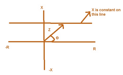
Form the characteristics it is clear that if the impedance vector head lies on the parallel line, this will have constant Reactance X. The important thing which should be noted from the characteristics that Resistance component of Impedance has no effect on the operation of Relay. The Relay will operate for all impedance whose head lies below the operating characteristics whether above or below R axis.
As seen above, this Relay is non directional Relay which means that this Relay will not be able to discriminate the fault on Transmission line, whether the fault is in the section where the Relay is located or in the adjoining section.
It is not possible to use directional element along with this Relay. This is because if we use directional relay with the Reactance Relay then Reactance Relay will operate even under normal loading condition if the system is operating at or nearer to unity power factor. The Relay used to give the directional feature in the Reactance relay is called MHO Relay.
MHO Relay:
In MHO Relay, the operating torque is obtained by the V-I element and Restraining torque by the Voltage element. This means MHO Relay is Voltage Restrained Directional Relay.
From Universal Torque Equation,
T = K1I2+K2V2+K3VICos(Ɵ-Ƭ)+K4
Putting K1 = 0, K2 = -1 and K4 = 0 we get the Torque in MHO Relay as
T = K3VICos(Ɵ-Ƭ) – K2V2
For Relay to operate,
T > 0
K3VICos(Ɵ-Ƭ) – K2V2 >0
K3VICos(Ɵ-Ƭ) > K2V2
V2/VI < K3Cos(Ɵ-Ƭ)/K2
V/I < (K3/K2)Cos(Ɵ-Ƭ)
But Z = V/I
So, Z < (K3/K2)Cos(Ɵ-Ƭ)
Operating Characteristics of MHO Relay:
The operating characteristics when drawn on R-X diagram is a circle passing through the origin. We can draw this by using the relation Z < (K3/K2)Cos(Ɵ-Ƭ)
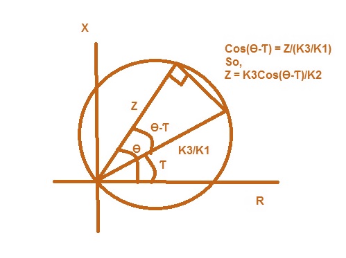
From the characteristics diagram, we observe that MHO Relay will operate if the impedance seen by it is within the circle. It is also obvious from the diagram that the Relay is direction itself (see by drawing a Zero Torque Line). Therefore we don’t need any directional element for MHO Relay.
The impedance seen by the Relay depends upon the type of fault. If it is Three Phase fault then the Relay will see positive sequence impedance and if it is line to ground fault then the Relay will see sum of positive, negative and zero sequence impedance. Thus for actuation of the relay different setting of impedance is required for different type of fault. But for making the Relay to have same sensitivity for all type of fault it is necessary for relay to measure a common impedance in all types of fault which is positive sequence impedance. Thus for all type of fault the relay will measure the positive sequence impedance and if the positive sequence impedance is sensed less than the setting in the Relay, then relay will issue a Trip command.
Thank You!!!
Why is it called mho relay, if it’s operation depends upon the value of impedance.
Because it measures component of admittance not impedance.