Distance protection is a non-unit system of protection offering considerable economic and technical advantages. Unlike phase and neutral over current protection, the key advantage of distance protection is that its fault coverage of the protected circuit is independent of source impedance variations. Let us take an example of this to understand how distance protection is independent of source impedance. Consider the figure below.
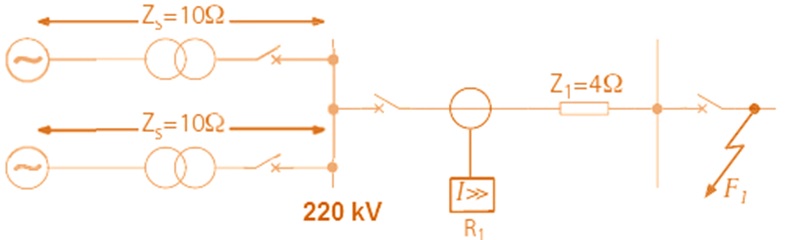
In the figure above, R1 is an over current relay which is used for the protection of Transmission Line. If there is a fault at F1,
Equivalent source impedance Zs = 10×10/20 = 5 Ω
Impedance up to the point of Fault = 5+4 = 9 Ω
Fault current IF1= 220×103/1.732*9 = 220×103/15.588 = 14113.5 A
Therefore the setting of over current Relay should be more than 14113.5 A.
Now consider the case,
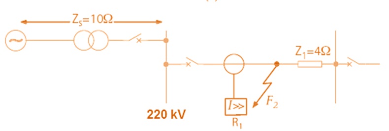
Here fault is not on the Transmission Line but it is assumed to be inside Switchyard and only one source is feeding the power to the network. Proceeding in the similar manner,
Fault Current IF2 = 220×103/1.732*10 = 12702A
Distance protection is therefore used for the protection of Transmission Line. It is simple to apply and fast in isolating the faulty section from the healthy network. Distance Protection provides primary as well as back-up protection to the protected line. I will show this back-up protection function latter in this post.
PRINCIPLE OF DISTANCE RELAYS:
Since the impedance of a transmission line is proportional to its length, for distance measurement it is justified to use a relay capable of measuring the impedance of a line up to a predetermined point. This predetermined point is called Reach of the Relay.
Such a relay is described as a distance relay and is designed to operate only for faults occurring between the relay location and the selected reach point, thus giving discrimination for faults that may occur in different line sections. The basic principle of distance protection involves the division of the voltage at the relaying point by the measured current. The apparent impedance so calculated is compared with the reach point impedance which is settable in the Relay. If the measured impedance is less than the reach point impedance, it is assumed that a fault exists on the line between the relay and the reach point and issues trip command to the concerned Breaker Trip Coil either through Master Trip Relay or directly (in case of single pole tripping of breaker, assuming single pole Auto Reclosure is allowed).
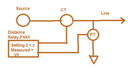
If measured value of impedance V/I is less than setting z then Relay assumes a fault as clear from the above diagram.
ZONE CONCEPT IN DISTANCE PROTECTION:
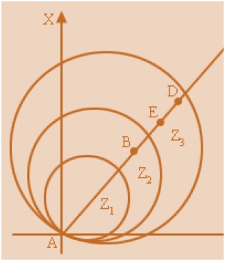
Consider the figure below and carefully observe.
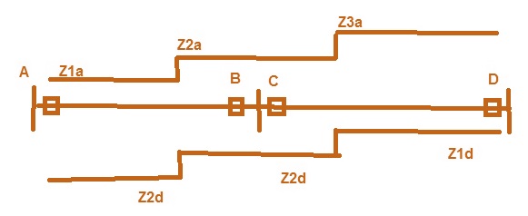
Here there are three sub-stations namely A, B and C. For sub-station A, the distance protection is divided into three zones Z1a, Z2a and Z3a which are called Zone-1, Zone-2 and Zone-3 protection. Similarly for sub-station D the three zones will be Z1d, Z2d and Z3d.
Zone-1 is normally set to 80% of total length of Line (here line length is AB between two consecutive substation). Zone-2 is set to 120 % of total line length or protected line plus 50% of shortest adjecent line whichever is greater and Zone-3 set at 120% of (100% line length + 100% of Longest Line from Remote substation i.e. B). It should be noted that all Zones are setting is done in terms of impedance.
Assume the distance between A and B = 200 KM
Total Impedance of Line AB = 61 Ohm
Current Transformer ratio = 1000/1A
Potential Transformer ratio = 400 kV / 110 V
So for Zone-1 Impedance setting = 80 % of Total Line Impedance = 80% of 61
= 0.8×61 = 48.8 Ohm ????? (Will it be????)
It won’t be…..because you need to consider CT & PT ratio for calculating the impedance as the Relay is sensing current and voltage through CT and PT only.
CT/PT Ratio = 1000/(400×103/110) = 1000×110/400,000 = 0.28
So the required setting for Zone-1 = 48.8×0.28 = 13.66 ohm. Which means if the distance Relay senses Impedance less than 13.66 Ohm then it will pick-up for Zone-1.
In the same manner, Setting for Zone-2 = (150% of 61) × CT/PT ratio
= 1.5×61×0.28 = 25.62 ohm
Which means if the distance Relay senses Impedance less than 25.62 Ohm then it will pick-up for Zone-2.
Setting for Zone-3 = 120% of (Impedance of Line AB+ Impedance of Longest Line from substation B)
Assume the Longest Line from substation B is having an impedance of 61 Ohm.
Therefore Setting for Zone-3 = (120% of (61+61)) × CT/PT ratio
= 1.2×122×0.28 = 41 Ohm
Which means if the distance Relay senses Impedance less than 41 Ohm then it will pick-up for Zone-3.
So we now know how to calculate the setting for different Zones of Distance Protection.
Now suppose our substation is A and we are providing distance protection so Relay is located at A. For fault in Zone-1, obviously we need to isolate the fault without any time delay. Now say our breaker at A opened but as we are connected to the substation B so their breaker at B shall also trip so as to isolate the fault completely otherwise fault will be feed from substation B side even though our breaker at A opened. Thus if fault in Zone-1 occurs then Distance Relay shall trip Breaker at A and send a signal to Remote Substation B by receiving which Remote substation B shall trip their breaker at B. This signal is called Carrier Signal which is sent through Power Line Carrier Communication (PLCC) Line. This is the purpose of PLCC.
Thus for Zone-1, time delay = 0. Got it? (If no then write in comment box I will be happy to clear your doubt)
Next, suppose there is a fault in Zone-2 then our breaker at A shall not trip rather Remote Substation breaker at C shall trip (If fault is in section CD in figure above) as it will be in their Zone-1. So we need to introduce some time delay in our Distance Relay to operate for Zone-2 fault. This time delay is usually kept around 350 ms. If within 350 ms Remote substation breaker at B trips then our Breaker at A won’t trip but if suppose because of any Reason Remote Substation breaker at C fail to trip then our breaker at A will definitely trip.
See how Zone-2 is working as Back-up protection for line CD. Got it friend?
Now if there is a fault in the remaining 20% of line which is protected by Zone-1 at our substation A then it will be sensed by our Relay at A in Zone-2 but for Remote substation B it will be Zone-1 so their breaker at B will instantaneously trip but our breaker at A also need to trip otherwise our substation will continue to feed the fault by receiving carrier signal.
Now coming to Zone-3, if there is a fault in Zone-3 then our breaker at A is not supposed to trip rather Remote substation breaker at C &D is supposed to trip. Therefore we introduce some time delay for the operation of Zone-3 which is typically of the order of 1s. If because of any reason breaker at C & D fail to trip within 1s then our Distance relay will operate to open our Breaker at A.
There is one more Zone in modern Distance Relay which is called Reverse Zone or Zone-4. As the name Reverse Zone implies it is back-up protection of the Substation where Distance Relay is installed, in our case to the substation A. The setting for zone is normally 10% of the impedance of protected line.
Distance Relay Zone Characteristics on R-X Plane:
The reach point of a relay is the point along the line impedance locus that is intersected by the boundary characteristic of the relay.
Thank you! Waiting for your comments…….
Hi your explanations are really good. But i need some more clarity in Zone 3 operation, could you explain me in brief? Also please do let me know how busbar differential works, if you have any explanation like this please share. My email [email protected]
Thank you! Let me take a real situation which we are adopting for new Switchyard. There are four zone of protection Zone-1, Zone-2, Zone-3 and Zone-4. Zone-3 setting is done in such a manner that it should operate when there is a fault on Remote end. Like if the distance between station A and station B = 200 Km and the longest line from station B is of 201 km (say station C) then as per the setting when a fault occurs in a line at station C then Zone-3 shall operate but first we shall wait for the operation of Zone-1 of station C and Zone-2 of station B, therefore a delay of 1 s is introduced in Zone-3. This is basically time grading. Hope it might help you.
For bus bar differential protection, I will say that it is much easier and will post on it soon and send you a doc. Thank you very much gain.
Such a good explanation……& examples….
Great description!!
Great description!!
Thank you Aditya for providing valuable information
I have one query.
as per the explanation, distance Zone reach settings are
Z1=13.66 ohms, Z2=25.62 ohms, Z3=41 ohms.
Consider If the fault occurs on Zone1, so let us assume the impedance seen by the relay will be around 10 Ohms.
So obviously this value (10 Ohms) lies under all the zone-1,2&3 settings.
So I understand that Z1 will operate at 0 seconds and zones (Z2 & Z3) will start and it will trip the breaker as per its time settings only when its remote breaker fail to open or fault still exists in the line.
Is my understanding is correct?
Yes Amaan. You are correct!
Hi Aditya,
Great explanation
Some concerns with regards to the consideration of the CT/PT ratio in calculating the setting for the Line Impedance. Is there a standard where it is based? Since as i always do in practice particularly in testing distance relays, i always consider the percentage of the line not considering the CT/PT ratio, please advise
Thanks
Rudolf
Great this what I was searching for …. I think I will visit your blog regularly.
Thank you very much for this information sharing.
Nagaraju
Thank you KORATA NAGARAJU!
Great explanation please provide such kind of information regularly. kindly provide same for power swing and out of step protection
Thank you Akhilesh! You can read about Power Swing and Out of Step Protection.
Sir your Post’s are always very useful such a great job .I have doubts in calculating line impedance ,positive ,negative,and zero sequence resistances ,reactance, impedance ,so post how to calculate this things
Thank you Mohan Raj!
Sir
How does plcc works ?? If fault occures in AB section then automatically A & B station relay operates then what is use of sending signal by plcc
Good question Sandeep. For better understanding, let me explain you few things:
1. Auto Reclousre is used in Zone-1. Agree?
2. Zone-1 of station A may be Zone-2 of station B. Agree?
So if there is a single phase fault in Zone-1 of station A, station A will initiate Auto Reclosure. But for station B, the fault is in Zone-2, hence it will initiate three phase trip. So altogether there is no benefit of having auto reclosure. Therefore, in such case, a signal is sent by PLCC to the remote station B to confirm that station B should also initiate auto reclosure. Did you understand? Please ask if you need more clarification.
Where is the reach of Zone 4 in distance relay characteristic curve? If there is a transformer connected at A, should we also consider it’s impedance in calculation of Zone 4 distance?
Where is the reach of Zone 4 in distance relay characteristic curve? If there is a transformer connected at A, should we also consider it’s impedance in calculation of Zone 4 distance?
generally the setting of Zone-4 protection is set at 10 percent of the line impedance or 10 percent of the shortest line connected whichever is minimum. This means that if the value of 10 percent of line impedance is more than 10 percent of line impedance of shortest line, then second one will be set. This is generally philosophy adopted, though the setting is dependent on the protection scheme.
Zone-4 may be seen in the distance relay characteristics. If you see the quadrilateral characteristics, zone-4 is in third quadrant.
If you need more clarification, please ask. Thank you!
what is meant by reverse reactance charecteristic? Is it related to the Zone 4 as reffered above?
Email me :hariukrishnan[@]gmail[dot]com
Very good explanation
Thank you Manju! Please share if you liked it.
Why some of the relays like Micom P442 required resistive reach settings although we have already added impedance pickup. Explain the significance of resistive reach for phase and ground faults.
I will publish a post on the significance of resistive reach setting. Please visit regularly.
Sir it means for every zone there is setting that it Sense only a particular zone impedance????
If it’s not than supposed relay is sensing 13.66 ohm it is less than zone-2 impedance than it will pick up for zone-2…
I can’t understand these kindly give concepts for this
There are different impedance setting for different Zones in Distance Relay. For your example, the impedance seen by Relay is equal to Zone-1 setting, therefore it will pick-up in Zone-1. If the impedance sensed by relay is more than 13.66 but less than 25.62 (Zone-2 setting), Zone-2 will pick up. Did you understand? Please revert if you still have doubt.
Impedance=V/I. than for calculating PT/CT ratio is (400*1000)/110 divided by1000/1. But above there is reverse of it. Can you provide your mobile no.
Good question! See, here the impedance calculated on the basis of primary is to be converted into secondary. For this, you need to convert primary voltage into secondary (110xV/400 kV where V is primary Voltage) and primary current into secondary (I/1000 where I is primary current). So Impedance in secondary will be ratio of secondary voltage and current.
This ratio i.e. Impedance in secondary terms
= (V/I)x{1000/(400 kV /110 V)}
= (Impedance in Terms of Primary) x (CT/PT Ratio)
Hope it is clear now. Please ask if you are still having any doubt. Your voice will never be lost at this blog. Request you to please share this blog in your facebook wall. Thank you!
Sorry sir I can’t understand!!
No problem Imran, I will further clarify. First think of converting primary voltage and current into secondary. If the PT is having ratio of 400 kV / 110 V, then if primary voltage is V then corresponding PT secondary voltage will be {Primary Voltage / (400 kV / 110 V)} = (Primary Voltagex110 V) / (400×1000). Similarly, the primary current can also be converted into secondary. If CT ratio is 1000 / 1, the secondary current will be (Primary Current / 1000) A.
Thus the impedance seen by relay = Secondary Voltage / Secondary Current
= [(Primary Voltagex110 V) / (400×1000)] / {(Primary Current / 1000)}
= {Primary Voltage/Primary Current}x {110×1000 / (400×1000)}
= (Impedance in terms of Primary or Line Impedance Setting)x {110×1000 / (400×1000)}
Here, {110×1000 / (400×1000)} is the multiplication factor to convert the impedance setting in primary to what to be set in relay in terms of secondary. Did you understand now?
Sir how PLCC work for protection purpose???
Please read the earlier reply to comment by Sandeep. If you still find problem, please ask.
Setting for Zone-3 = 120% of (Impedance of Line AB+ Impedance of Longest Line from substation B)
What is the longest line from Substation ?????.
Substation may be connected through n different lines. Here longest line connected to remote substation should be considered. Did you get it? Please reply.
Than 61 ohm should not be impedance of longest line!!!!
Refer “Assume the Longest Line from substation B is having an impedance of 61 Ohm”, hence it is impedance of longest line from remote sub-station B.
Next, suppose there is a fault in Zone-2 then our breaker at A shall not trip rather Remote Substation breaker at C shall trip (If fault is in section CD in figure above) as it will be in their Zone-1. So we need to introduce some time delay in our Distance Relay to operate for Zone-2 fault.
how sec-CD is in zone-1?????
There is a time delay in Zone-2. CD is not in Zone-1 for relay at A breaker side.
Assume a situation in which there is a line to ground fault in a 33 kv feeder…….somehow 33 kv breaker is unable to clear it….then the fault will pass to the t-d transformers…which are also unable to clear it…..will in that case our 132 kv line distance protection at the local end operate in Z1 or Z4…???? Or will the other end protection operate in Z2 or Z3….????
Zone-4 will not operate but the protection of 132 kV line will operate on Zone-2 depending on the scheme.
great effort. clear concept
Thanks mate, really good effort and and nice demonstration, keep it up!
Thank you. You are requested to kindly read “A Case Study on LBB Protection Logic” and give your opinion.
Nice explanation .
can you explain further about Zone 4.Why it is called as back up protection?.
Thank you! Zone-4 protects the switchyard and it is a time delayed protection. This is the reason it is called backup protection.
IS IT POSSIBLE TO ENABLING Z4 REVERSE AND GATE ALL BAY IN ONE SUBSTATION FOR PROTECTING BUS BAR INSTANT?
I could not get you point. Kindly explain.
Very NICE explanation of distance Protection concept. Thanks for sharing the knowledge.
Kindly share if you like the post. It will help us to reach more.
Nice and clear explanation
“Therefore the setting of over current Relay should be more than 14113.5 A.”,
why not O/C setting less than that value?
Can we use distance protection on 25 km long, 33 kV Transmission line?
helloo, great explanation ! thankyou
If power transformer is attached in the middle of A-D Line above, How to calculate Zone 2 and Zone 3 ?
Could anyone please explain “Therefore the setting of over current Relay should be more than 14113.5 A.”?