Revolving Field Theory is used for the analysis of behavior of Single Phase Induction Motor. Before going into the details of Revolving Field Theory, first we should know why do we need to study this theory?
Well, a Single Phase Induction Motor with its main winding alone can be represented as shown in figure below.

When a Single Phase Induction Motor is supplied with a voltage source to its stator, an alternating flux is developed by the stator in the air gap which is stationary but pulsating in nature. This flux links with the Rotor winding and produces a current in the rotor bars. For the assumed direction of stator flux Øs as shown in figure above, the current distribution along the periphery of the Squirrel cage Rotor bars will be as shown in figure. This distribution of current in the rotor produces a flux Ør. Notice that the direction of rotor produced flux Ør is in opposition with the stator produced flux Øs which is in accordance with the Lenz’s law.
As we know that torque produced in any electrical machine is directly proportional to the sine of Torque Angle α, i.e. Sinα (Torque Angle is defined as the angle between the Stator Flux and Rotor Flux). In our case Torque Angle α = 180°, which means that no torque will be produced as Sin180° = 0.
Thus we can explain why Single Phase Induction Motor is not self starting. But once an Induction Motor is started by any means in any direction, it continues to run in that direction. How can we explain this amazing feature of Single Phase Induction Motor? To explain this, we need the concept of Revolving Field Theory.
You may like to read, Why 3-Phase Induction Motors are Self-Starting but 3-Phase Synchronous Motors Not?
Now we are at a stage to discuss Revolving Field Theory. According to Revolving Field Theory, the stationary pulsating mmf wave can be resolved into two counter rotating mmf waves of equal amplitude but revolving at a synchronous speed.
Let us assume that stator mmf wave be sinusoidally distributed in the space and varying in sinusoidally in time. So mathematically we can write stator mmf wave as,
Fs = FsmaxSinwtCosƟ
Where Fsmax is the peak value of mmf corresponding to maximum instantaneous current in the stator winding and Ɵ is the space displacement angle measured from the stator main winding axis.
As we are well aware from Trigonometry that,
2SinACosB = Sin(A+B) + Sin(A-B)
Thus, SinACosB = [Sin(A+B) + Sin(A-B)] / 2
Therefore, stator stationary but pulsating mmf wave can be written as,
Fs = (1/2)FsmaxSin(wt-Ɵ) + (1/2)FsmaxSin(wt+Ɵ)
The first term (1/2)FsmaxSin(wt-Ɵ) is the forward rotating mmf wave and second term (1/2)FsmaxSin(wt+Ɵ) is the backward rotating mmf wave. How am I saying this? How can I judge which one is forward rotating and which one backward rotating?
This is quite simple to explain and understand. Let us take Ɵ = 30° and fix it and vary the value of wt.
|
Value of wt
|
Value of (1/2)FsmaxSin(wt-Ɵ) at Ɵ = 30°
|
|
0
|
-0.25Fsmax
|
|
30°
|
0
|
|
60°
|
0.25Fsmax
|
|
90°
|
0.433Fsmax
|
Thus from the above table, we observe that value is progressively increasing or sinusoidal curve is moving from left to right. This is reason we say (1/2)FsmaxSin(wt-Ɵ) is the forward rotating mmf wave.
|
Value of wt
|
Value of (1/2)FsmaxSin(wt+Ɵ) at Ɵ = 30°
|
|
0
|
0.25Fsmax
|
|
30°
|
0.433Fsmax
|
|
60°
|
1
|
|
90°
|
0.433Fsmax
|
From the above table, sinusoidal curve is moving from right to left. This is reason we say (1/2)FsmaxSin(wt+Ɵ) is the backward rotating mmf wave.
Can I expect that you have understood the concept of Revolving Field Theory? Please write in comment box.
Now we will use Revolving Field Theory to explain why an Induction does Motor continues to run when started by any means in any direction?
Because of forward and backward stator mmf wave, there will be two fluxes, one rotating in forward direction and another in backward direction. Thus we can assume torque production by the individual fluxes and then superimpose them for getting the resultant Torque Slip Characteristics of Single Phase Induction Motor. It may be noted at this point that forward and backward fluxes are equal in magnitude when the motor is at standstill condition while at all other rotor speed the forward flux wave is much larger than the backward flux wave.
The forward torque Tf and backward torque Tb will be in opposite direction as shown in figure below.
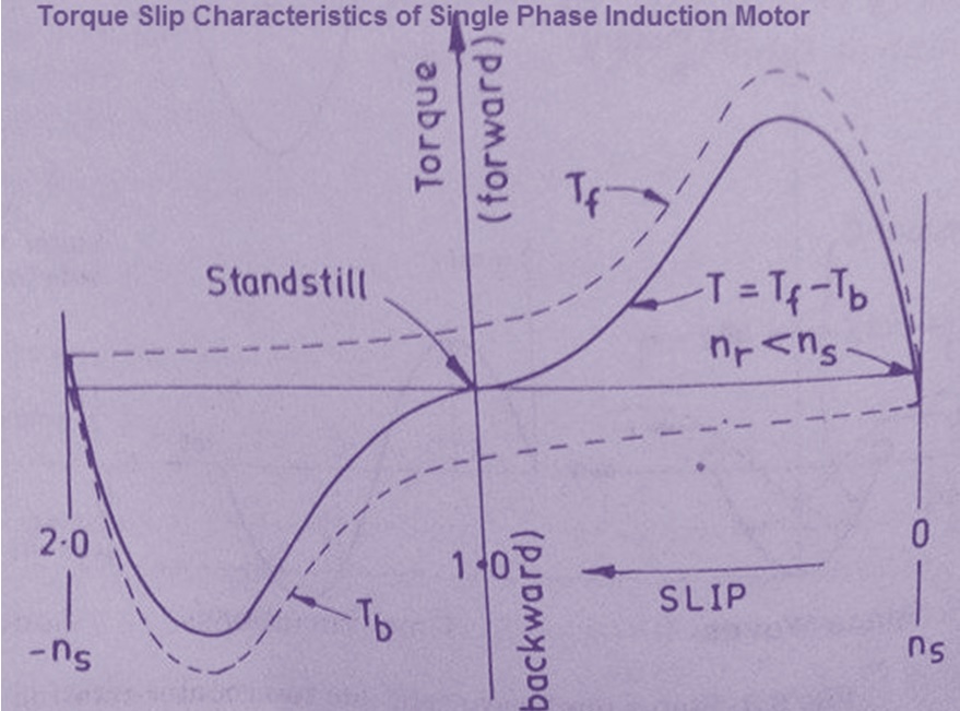
From the above, torque slip characteristics, it is quite clear that at standstill condition the net torque is zero while at any speed of rotor there exists a torque. Also notice that torque exists in both the directions and this is the reason when a single phase induction motor, started by any means in any direction continues to rotate.
Hope you enjoyed the post. Please write your views in the comment box.
Awesome explanation
Given that easy to understand but it not enough we require some explanation
Thanks
easy and awesome.. really enjoyed it.
Thank you! Please share if you like it.
Very easy to understand. Great explanation. Thank you for making the effort to share it.
Above table information is wrong because sin90 is 1 and you wrote there 0 in the third column of 2nd table because sin(wt+Ɵ) should be 90° if wt is 60° and Ɵ is 30°
Thanks for pointing out. necessary correction has been done.