As discussed in earlier post Revolving Field Theory of Single Phase Induction Motors, a single phase induction motor with main stator winding alone has no inherent starting torque as the main stator winding only produces stationary pulsating air gap flux wave. For the development of starting torque, rotating field at the starting must be produced. There are various methods of starting a single induction motor, which can be classified as below,
1) Split phase starting
2) Shaded pole starting
3) Repulsion motor starting
4) Reluctance starting
Generally a single phase induction motor is known by the method employed for its starting. Basically the selection of a particular single phase induction motor and choice of its starting method depends upon the following factors:
1) Torque speed characteristics of load from starting to normal operating speed
2) The duty cycle
3) The starting and running line current limitation as imposed by the supply authorities
In this post we will only discuss the Split phase starting of single phase induction motor.
Single Phase Induction Motor employing split phase starting method is known as split phase motor. All the split phase motors have two winding, main winding and auxiliary winding. Both theses windings are connected in parallel but their magnetic axis are displaced by an angle 90°. Split phase starting method is further categorized into following:
1) Resistor split phase motors
2) Capacitor split phase motors
3) Capacitor start and run motors
Resistor Split Phase Motors:
A schematic diagram of the two stator winding in quadrature is shown if figure below. Subscript m and a stands for main and auxiliary winding of stator. CS is Centrifugal Switch.
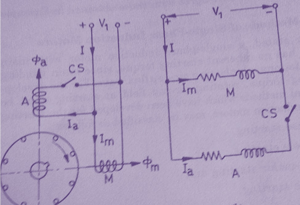
As we know that, if the two winding currents are shifted in time phase, a rotating filed is created which is necessary for the production of starting torque. In order to achieve this main winding M is designed to have low resistance but higher reactance whereas the auxiliary winding is designed to have higher resistance (thin wire) but lower reactance. The use of thin wire for auxiliary winding is acceptable as auxiliary winding only remain in circuit during starting but the use of thick wire for main winding is necessary as main winding has to remain in circuit permanently. As the reactance is directly proportional to the square of number of turns, auxiliary winding has less number of turns as compared with main winding.
In addition to the above mentioned points, leakage reactance of main winding is increases by placing it at the bottom of slot whereas auxiliary winding is placed at the top of slot to have low leakage reactance.
As seen in above discussion, main winding has more reactive impedance as compared to the auxiliary winding, therefore main winding current Im lags behind the auxiliary winding current Ia as shown in the phasor diagram below.
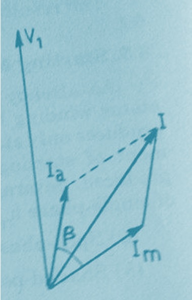
Thus from the phasor we see that the angle between the two field produced by main and auxiliary winding is β. As we know that torque produced is directly proportional to torque angle which is β here, therefore a n net starting torque will be developed. The auxiliary winding is disconnected automatically by means of Centrifugal Switch CS at about 70-80% of synchronous speed. If the Centrifugal Switch fails to operate, auxiliary winding will remain in the circuit and noisy performance of single phase induction motor will result. Since auxiliary winding is short time rated, it must get overheated and consequently burn out.
Typical application of Resistor split phase induction motor is for fans, blowers, centrifugal pumps and refrigerator.