Definition:
RTD stands for Resistance Temperature Detector. RTD sensor is basically a temperature sensing device in which change in resistance of the detector element is calibrated with temperature. Thus, a change in resistance directly gives the value of temperature of the system. It is used to measure the temperature of a system and also known as Resistance Thermometer.
Specification of RTD Sensor:
An RTD sensor is specified in terms of its nominal resistance at 0 °C, Temperature Coefficient of Resistance (TCR) and Tolerance Class. Nominal resistance is the resistance of sensing element at 0 °C. For example, in pt100 RTD, the nominal resistance is 100 Ohm at 0 °C and the material is platinum.
TCR is the change in resistance with per unit change in temperature. This value should be as high as possible. Platinum has TCR equal to 0.00392. This means that, the resistance of platinum wire will change by 0.00392 Ohm when temperature changes by 1 °C.
Tolerance Class is the accuracy of RTD at nominal temperature i.e. 0 °C. It is defined in IEC 751 for platinum RTD. The accuracy of pt RTD at 0 °C is ±0.3 °C.
Sensing Element of RTD:
RTD element is made up of platinum, copper or nickel. Balco is also used as the sensing element. Balco is a nickel-iron alloy with a thermal conductivity similar to nickel but twice the resistivity.
Criteria for Selection of Sensing Material:
The requirement of a conductor material to be used in RTDs are as follows:
- The change in resistance of material per unit change in temperature should be as high as possible. This property provides better response and sensitivity to the temperature sensor.
- The material should have high value resistivity so that minimum volume of material is required for the construction of sensor.
- The resistance of material should have a continuous and stable relationship with temperature. Stable relationship of resistance and temp. is important from repeatability point of view. In case, this relationship changes, the reading will not be stable.
- The material should be chemically stable. It should not get corroded with temperature.
Platinum is the widely used material as Resistance Thermometer material. However, copper and Nickels are also used for some application. Platinum RTD is used for temperature range of -200 °C to 800 °C. However, in industrial application, pt100 is used up to around 400 °C. At higher temperature, the accuracy of pt100 deteriorates and hence not preferred. Thermocouple is suitable choice for temperature measurement at higher temperature.
Characteristics of RTD Element:
As discussed above, the relationship between temperature and resistance of sensing element should be linear and stable. Therefore, the material whose temperature versus resistance characteristics is linear up to higher temperature is most suitable. Figure below depicts the characteristics for copper, platinum, Nickel and Balco.
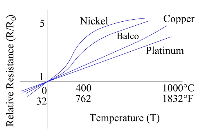
It can be seen that; platinum is having the linear relationship up to 1000 °C. This is one of the reason that it is preferred material for temperature sensing element. Apart from this, pt is shows limited susceptibility to contamination and can withstand high temperature while maintaining excellent stability.
Construction of RTD Sensor:
RTD Sensor is available in two different type of construction: Wire Wound and Thin Film. In wire wound construction, the temperature sensing element is wound in the form of coil on a ceramic or glass cylinder which is then insulated.
In thin film construction, the temperature sensing element is etched onto a ceramic substrate. This is then trimmed with laser to achieve the desired nominal resistance. The ceramic substrate and the sensing wire are then protected using thin layer of glass. This type of construction is most used due to its economy and increased resistance for a given size. If you get a chance, look at the catalogue of an RTD and check out its specification. You will get better insight of the RTD.
Working Principle of RTD:
The working principle of RTD is based on the fact that the value of resistance of a conductor changes with temperature. This property is utilized for measurement of temperature. Increase in temperature of a system, increases the value of the resistance element. Similarly, a decrease in temperature results in decreases in the resistance of temp. sensing element.
The variation of resistance R with temperature T (°K) can be represented by the following relationship for most of the metals as:
R = R0(1+α1T+α2T2+……..+αnTn+…)
where R0 = Resistance at temperature T = 0 and α1, α2,… αn are constants.
How RTD sensor Works?
As we know, RTD sensor is used to measure system temperature. To measure the temperature, it is mounted in the system or strap on the system. A constant DC current is injected to the Resistance Thermometer. Due to this current, a voltage drop takes place across the resistance of the RTD. This voltage drop is measured using a transmitter. This voltage drop is then used to measure the temperature of the system.
It should be noted here that, current causes ohmic heating and hence the heat generated may rise the temperature of the sensing element and hence the reading provided by the RTD may not represent the actual system temperature. To avoid this kind of error due to self-heating, very small DC current (generally 1 mA) is flown through the element.
An RTD can be connected in two, three or four wire configurations. An RTD having only two leads are called two wire RTD. Similarly, an RTD having three and four wires are known as three wire and four wire RTD respectively.
2 Wire Configuration:
Two wire RTD is the most common type of RTD and very prone to measurement error. Lets us consider a simple circuit of two wire RTD configuration for better understanding.

Constant DC current I is injected in the RTD through its connecting leads and the voltage drop is measured across AB. The voltage drop across AB will correspond to the combined voltage drop in RTD resistance and lead resistance. Thus, the resistance measure will be the total resistance instead of resistance of sensing element. As voltage drop is calibrated with the system temperature, hence the temperature measured by 2 wire configuration will not represent the actual temperature rather it will show temperature more than the system temperature. This configuration is rarely used for temperature measurement in industries. However, where accuracy is not so important, only an idea of temp. is required, one may be used 2 wire configuration.
3 Wire Configuration:
Three wire RTD configuration is the most commonly used configuration in industries. In this configuration, three leads come out of the RTD Sensor. A three wire RTD is shown below.

As can be seen, two wires are connected to one end of RTD element and one wire to the other end of the element. These wires A, B and C connects the sensing element to the monitoring element. Since, sensing element may be in filed whereas the monitoring devices are located in Control Room, the resistance of connecting lead may cause error in the measurement and hence lead resistance must not be accounted by the monitoring device for accurate temperature measurement. This achieved by three wire RTD.
In this RTD, three identical wires of equal lengths are used so that their lead resistance are equal. Let the lead resistance be RL and the resistance of RTD element to be measured is R. By measuring the resistance between A & C, we have (2RL+R) whereas measurement of resistance across A & B gives (2RL). The two values when subtracted will give the accurate measurement of RTD element i.e. R. This principle is used in 3 wire RTD configuration for accurate temperature monitoring.
4 Wire RTD Configuration:
In this configuration, four wires are used to accurately monitor the temperature. This configuration gives the most accurate result but is complex from installation point of view. Figure below shows 4 wire configuration.
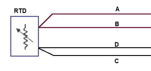
Constant DC current is injected through outer leads A & C whereas the voltage drop across the sensing element is measured through inner leads B & D. Since the voltmeter have a large value of resistance, the flow of current through the voltage measuring lead B&D will be negligible and hence the measured voltage may be treated as the voltage drop across the RTD element.
Since voltage drop across the RTD element and current through it are known, the resistance can be easily found using (V/I) and hence the temperature of system.
Limitations of RTD:
The accuracy of RTD decreases at a very large temperature and hence use of RTD to measure high temperature results in inaccurate temp. measurement. It is preferably used for -200 °C to 800 °C. Thermocouple is best suited for large temperature measurement.
Awesome! Information. Great work thank you for sharing such useful information. keep it up all the best. I can also refer you to one of the Best Thermal sensors services in Hyderabad.