Definition
Silicon Controlled Rectifier (SCR) is a solid state device used for power control in DC and AC system. An SCR is so called because silicon is used for its construction and its operation as a rectifier can be controlled.
Silicon Controlled Rectifier is the oldest member of thyristor family. Thyristor is a family of solid state devices whose characteristics is similar to that of thyratrone tube. The construction of thyristor is similar to that of a Transistor. The name THYRISTOR has been derived from the first three letter of THYRatron and last four letter of transISTOR. Apart from Silicon Controlled Rectifier, there are various other members like GTO, TRIAC, DIAC etc. But the application of SCR is so huge that SCR has become synonym of thyristor. Thus the word SCR and thyristoir is interchangeably used.
Construction of Silicon Controlled Rectifier
A Silicon Controlled Rectifier or SCR consists of three p-n junctions and have two stable states, an ON state and an OFF state and can change its state from one to another. It has three terminals: Anode, Cathode & Gate. Figure below shows the constructional detail of SCR.
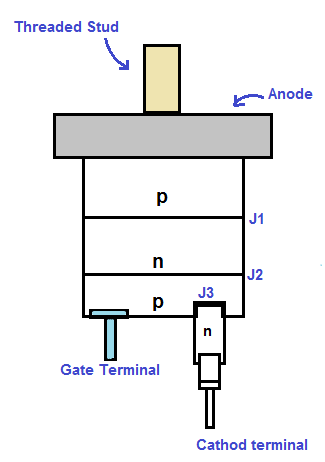
It can be seen from the above that SCR consists of four layers of alternate p-type and n-type semiconductors making three p-n junctions. These three p-n junctions are shown by J1, J2 & J3 in the above figure. The main purpose of threaded stud is to mount the SCR on heat sink. This is very important as the rating of SCR may be of the order of 10 kV and 3000 A which corresponds to power handling capacity of 30 MW. Therefore it is vital to make arrangement for the proper cooling of SCR. The threaded stud is used for mounting the SCR on heat sink to dissipate heat generated in it during its service.
Gate terminal is usually kept near the p-type semiconductor near to cathode terminal. The schematic diagram and circuit symbol of Silicon Controlled Rectifier is shown in Figure-1 & 2 respectively.
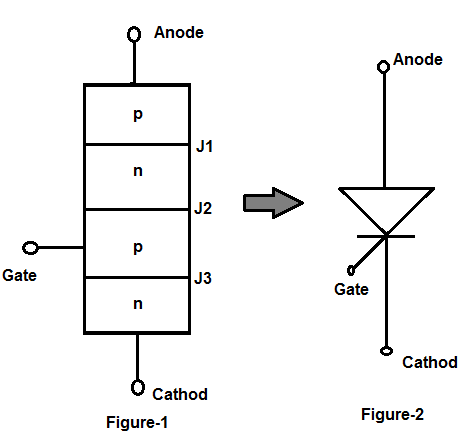
In the schematic diagram, the three terminal of SCR is shown to be Anode, cathode and Gate. The terminal connected to the outer region p is called Anode, the terminal connected to outer region n is called Cathode and that connected to inner p region is called Gate.
Like diode, SCR blocks the flow of current from cathode to anode in reverse conduction mode but unlike diode it also blocks the flow of current from anode to cathode until it is triggered into conduction by proper gate signal between gate and cathode terminal of SCR.
When the anode is positive with respect to cathode with gate circuit open, the SCR is said to be forward blocking mode. Similarly, when Anode is negative with respect to cathode, it is said to be in Reverse Blocking Mode. In both the modes, it does not conduct. In Forward Blocking Mode a positive signal is applied at Gate terminal to bring the SCR conduct in forward conduction mode. In forward conduction mode, it behaves like a close switch to allow the flow of current through it.