A single phase half wave controlled rectifier is a thryristor based circuit which produces output voltage for positive half of the supply voltage. However, the phase relationship between the initiation of load current and supply voltage can be controlled by changing firing angle. This is the reason; it is called phase controlled half wave rectifier. In this article, we will discuss the circuit diagram, average load voltage, average load current and RMS load voltage for a Single Phase half Wave Controlled Rectifier with RL load.
Circuit Diagram:
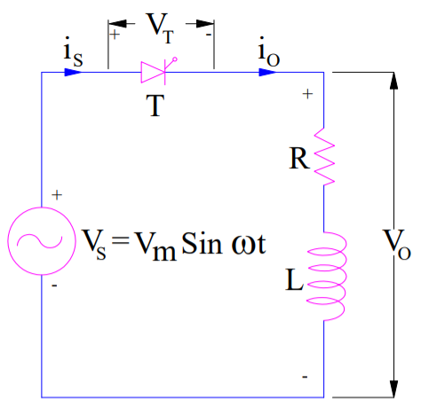
The circuit diagram of a single phase half wave controlled rectifier with RL load is shown below. This circuit consists of a thyristor T, source Vs and RL load. The output voltage is the voltage across the load and shown as Vo. Output current is the current through the load and shown as io.
Working Principle:
The waveform of source voltage, load voltage, load current and voltage across thyristor is shown below.
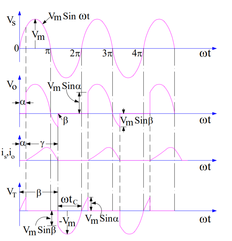
It is assumed that the thyristor T is fired at an angle ωt = α. As soon as the thyristor T is fired at ωt = α, load voltage equal to the source voltage instantaneously appears across the load terminal. This is because, the thyristor is forward biased in between ωt = 0 to α. Hence, once the thyristor is gated, it stars conducting.
However, the current does not start at this instant of firing. This is just because of the nature of load. Since, the load is inductive, it will not allow any sudden change. Therefore, at ωt = α, the output current will be zero and will gradually increase. The output current will become maximum and then start decreasing. It should be noted here that, this behavior of load current io will not be observed for purely resistive load.
At ωt = π, the load voltage Vo reduces to zero. However, the load current will not be zero at this instant because of inductance L. Due to this, thyristor will not turn off, even though it is reversed biased. Rather it will continue to conduct till ωt = β. At ωt = β, the load current becomes zero and thyristor is reversed biased, hence it will turn off. This is a case of natural commutation.
After ωt = β, vo = 0 and io = 0. At ωt = (2π+α), the SCR is triggered again, vo is applied to the load and load current develops as discussed before. The angle β where the load current becomes zero is called extinction angle and the angle (β-α) for which thyristor is ON is called conduction angle.
Carefully observe the voltage across the thyristor. The SCR is reverse biased from ωt = β to ωt = 2π. During this period, the current through thyristor is also zero. Therefore, circuit turn off time is tc = [(2π – β) / ω] second. This time must be greater than the thyristor turn-off time otherwise thyristor may turn on at undesired instant and will lead to commutation failure.
Calculation of Steady Load Current:
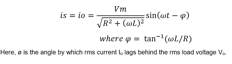
Steady state load current for single phase half wave controlled rectifier is given as below.
Calculation of Average Load Voltage and Current:
The average value of any function f(x) is given as below.
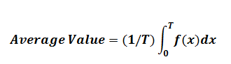
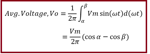
Now, we will apply the above formula to calculate the avg. load voltage of single phase half wave controlled rectifier with RL load. For this, carefully observe the waveform of load voltage. The time period of the voltage waveform is 2π and it is equal to VmSin(wt) for wt = α to wt = β. For 0<wt<α and β<wt<2π, the value of load voltage is zero.
Therefore, the average voltage of this controlled rectifier with RL load may be calculated as below.
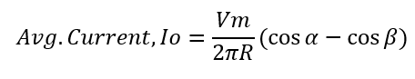
Average load current Io can be calculated by dividing the average load voltage by the circuit resistance. Mind that, average load current means DC quantity, therefore average voltage is divided by circuit resistance R instead of circuit impedance Z. Therefore, average load current of single phase half wave controlled rectifier is given as below.
Calculation of RMS Load Voltage:
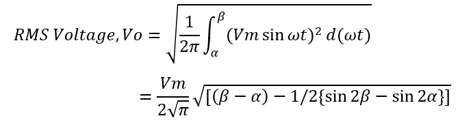
RMS load voltage of single phase half wave controlled rectifier is given as below.
Hope you enjoyed the article. In case you have any doubt/suggestion, kindly write in comment box. Kindly share the post if you like it.
that was very useful. thank you
how is the RMS current calculated?, just by divinding Vrms by the impedence?, or is there another formula for calculating it?
How can we calculate rms current.
Yeah, I think you just have to find the magnitude of the impedance of the circuit, divide Vrms and Impedance to find Irms.
Pls derive the average load voltage