Step-down cycloconverter is a device which steps down the fixed frequency power supply input into some lower frequency. It is a frequency changer. If fs & fo are the supply and output frequency, then fo < fs for this cycloconverter.
The most important feature of step-down cycloconverter is that it does not require force commutation. Line or Natural Commutation is used which is provided by the input AC supply.
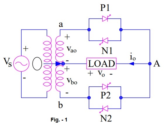
Circuit Diagram:
There are two circuit configurations of a step-down cycloconveter: Mid-point and Bridge type. This article, focuses on the mid-point type. The operation for continuous and discontinuous type of RL load is explained for mid-point type cycloconverter.
Figure below shows the circuit diagram of mid-point type cycloconverter. The positive direction of voltage and current are marked in the diagram.
Working of Step-down Cycloconverter:
The working principle of step-down cycloconverter is explained for discontinuous and continuous load current. The load is assumed to be comprised of resistance (R) & inductance (L).
Discontinuous Load Current:
For positive cycle of input AC supply, the terminal A is positive with respect to point O. This makes SCRs P1 forward biased. The forward biased SCR P1 is triggered at ωt = 0. With this, load current io starts building up in the positive direction from A to O. Load current io becomes zero at ωt = β>π but less than (π+α). Refer figure-2. The thyristor P1 is thus, naturally commutated at ωt = β which is already reversed biased after π.

After half a cycle, b is positive with respect to O. Now forward biased thyristor P2 is fired at ωt = (π+α). Load current is again positive from A to O and builds up from zero as shown in figure-2. At ωt = (π+ β), io decays to zero and P2 is naturally commutated. At ωt = (2π+α), P is again turned ON. Load current in figure-2 is seen to be discontinuous.
After four positive half cycles of load voltage and load current, thyristor N2 is gated at (4π+α) when O is positive with respect to b. As N2 is forward biased, it starts conducting but the direction of load current is reverse this time i.e. it flows from O to A. After N2 is triggered, O is positive with respect to “a” but before N1 is fired, io decays to zero and N2 is naturally commutated. Now when N1 is gated at (5π+α), io again builds up but it decays to zero before thyristor N2 in sequence is again gated.
In this manner, four negative half cycles of load voltage and load current, equal to number of positive half cycles of load voltage & current, are generated. Now P1 is again triggered to fabricate four positive half cycles of load voltage and so on. It may be noted that, natural commutation is achieved for discontinuous current load.
Form figure-2, the waveform of mean load voltage & current may be noted. It is clear that the output frequency of load voltage & current is (¼) times of input supply frequency.
Continuous Load Current:
When “a” is positive with respect to O in figure-1, P1 is triggered at ωt = α, positive output voltage appears across load and load current starts building up as shown in figure-3. At ωt = π, supply and load voltages are zero. After ωt = π, P1 is reversed biased. As load current is continuous, P1 is not turned OFF at ωt = π. When P2 is triggered in sequence at (π+α), a reverse voltage appears across P1, it is therefore turned OFF by natural commutation.

When P1 is commutated, load current has builds up to a value equal to RR. With the tun ON of P2 at (π+α), output voltage is again positive. As a consequence, load current builds up further than RR as shown in figure-3. At (2π+α), when P1 is again turned ON, P2 is naturally commutated and load current through P1 builds up beyond RS.
At the end of four positive half cycles of output voltage, load current is RU. When N2 is triggered after P2, load is subjected to negative voltage cycle and load current io decreases from RU to negative AB. Now N2 is commutated and N1 is gated at (5π+α). Load current io becomes more negative than AB at (6π+α), this is because with N1 ON, load voltage is negative. For four negative half cycles of output voltage, current io is shown in figure-3. Load current waveform is redrawn in the last waveform of figure-3.
It may be seen from the waveform of load current that it is symmetric with respect to wt axis. The mean waveform of load voltage is also shown in load voltage waveform. It is clear from the load current and mean load voltage waveform that the output frequency is one fourth of the input supply frequency i.e. fo = (¼)fs.
very excellent topic containt