There are three methods which are used for the measurement of three phase power in three phase circuits. The three methods are:
- Three Wattmeter Method
- Two Wattmeter Method
- Single Wattmeter Method
In this post, we will discuss the Two Wattmeter Method for power measurement.
Two Wattmeter Method:
In two wattmeter method, a three phase balanced voltage is to a balanced three phase load where the current in each phase is assumed lagging by an angle of Ø behind the corresponding phase voltage.
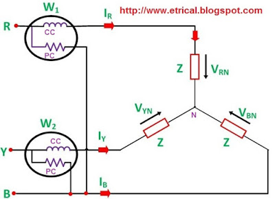
The schematic diagram for the measurement of three phase power using two wattmeter method is shown below.
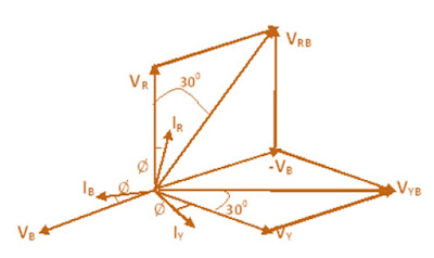
From the figure, it is obvious that current through the Current Coil (CC) of Wattmeter W1 = IR , current though Current Coil of wattmeter W2 = IB whereas the potential difference seen by the Pressure Coil (PC) of wattmeter W1= VRB (Line Voltage) and potential difference seen by Pressure Coil of wattmeter W2 = VBY. The phasor diagram of the above circuit is drawn by taking VR as reference phasor as shown below.
From the above phasor diagram,
Angle between the current IRand voltage VRB = (30° – Ø)
Angle between current IYand voltage VYB = (30° + Ø)
Therefore, Active power measured by wattmeter W1 = VRBIR Cos (30° – Ø)
Similarly, Active power measured by wattmeter W2 = VYBIYCos(30° + Ø)
As the load is balanced, therefore magnitude of line voltage will be same irrespective of phase taken i.e. VRY, VYB and VRB all will have same magnitude. Also for Star / Y connection line current and phase current are equal, say IR = IY = IB = I
Let VRY = VYB = VRB = VL
Therefore,
W1 = VRBIRCos (30° – Ø)
= VLICos(30° – Ø)
In the same manner,
W2 = VLICos(30° + Ø)
Hence, total power measured by wattmeters for the balanced three phase load is given as,
W = W1 + W2
= VLI×Cos(30° – Ø) + VLI×Cos(30° + Ø)
= VLI [Cos(30° – Ø) + Cos(30° + Ø)]
= 2VLI×Cos30°CosØ ……………….[ CosC + CosD = 2Cos(C+D)/2×Cos(C-D)/2 ]
=√3VLICosØ
Therefore, total power measured by wattmeters W = √3VLICosØ
Now, suppose you are asked to find the power factor of the load when individual power measured by the wattmeters are given, then we should proceed as
W1 + W2 = √3VLICosØ ……………………………..(1)
Similarly,
W1 – W2= VLI×Cos(30° – Ø) + VLI×Cos(30° + Ø)
= VLI [Cos(30° – Ø) + Cos(30° + Ø)]
= 2VLI×Sin30°SinØ ………[ CosC – CosD = 2Sin(C+D)/2×Sin(D-C)/2 ]
= VLISinØ
Hence,
W1 – W2 = VLISinØ ………………………………(2)
Dividing equation (2) by equation (1),
(W1 – W2) / (W1 + W2) = VLISinØ / √3VLICosØ
(W1 – W2) / (W1 + W2) = (tanØ) /√3
Hence,
|
tanØ = √3[(W1 – W2) / (W1 + W2)]
|
From the above equation, we can find the value of Ø and hence the power factor Cos Ø of the load.
Hope you understand the method of measurement of three phase power using two wattmeter method. Now we will consider three cases and will observe the how the individual wattmeter measures the power in each case.
Case1: When the power factor of load is unity.
As the power factor of load is unity, hence Ø = 0
Therefore,
Power measured by first wattmeter W1= VLI Cos(30° – 0)
= VLI Cos30°
= 0.866 VLI
Power measured by second wattmeter W2= VLI Cos(30° + 0)
= VLI Cos30°
= 0.866 VLI
Thus we see that, when the power factor of load is unity then both the wattmeter reads the same value.
Case2: When power factor of load is 0.5 lagging.
As power factor is 0.5 hence CosØ = 0.5 i.e. Ø = 60°
Therefore,
Power measured by first wattmeter W1= VLI Cos(30° – 60°)
= VLI Cos30° ……[Cos (-Ɵ) = CosƟ ]
= 0.866 VLI
Power measured by second wattmeter W2= VLI Cos(30° + 60°)
= VLI Cos90°
= 0
Thus we see that, when power factor of load is 0.5 lagging then power is only measured by first wattmeter and reading of second wattmeter is ZERO.
Case3: When power factor of load is zero.
As power factor of load is zero, hence CosØ = 0 i.e. Ø = 90°
Therefore,
Power measured by first wattmeter W1= VLI Cos(30° – 90°)
= VLI Cos60°
= 0.5 VLI
Power measured by second wattmeter W2= VLI Cos(30° + 90°)
= –VLI Cos60°
= -0.5 VLI
Thus we see that, when power factor of load is zero then one wattmeter reads +ive while second wattmeter reads –ive. As second wattmeter reads –ive hence wattmeter won’t read anything practically, therefore for second wattmeter we need to interchange the leads of either Pressure Coil or Current Coil so that second wattmeter may read value. As we have interchanged the connection of leads of either PC or CC, hence second wattmeter will read +ive but while calculating the total power measured we must take the reading of second wattmeter as –ive.
It shall be noted that when 60° <Ø < 90°, reading of one wattmeter will be positive while the reading of second wattmeter will be negative.
Hope you enjoyed this post. Please write your review and share this to your facebook wall. Thank you!


this is really helpful.
Good
thanks a lot
This is easily understandable
Good
great note! Simple but clear!
Thank you Tracey! Please share the post if you like it.
Super
Superb explanation
Calculation of case_2 is wrong. You have written cos30= 0.5 but in actual value is 0.866. please correct same. Ty
Thank you very much for pointing calculation mistake. Please check, the same has been rectified.
Nice
What are the advantages of this method?
Whenever we are saying that 2 watt meter method and 3 wattmeter method power is same.
so how can prove for
Case1. Unbalance current in all theree phase
case2. For 0.5 leg power factor total power with 3 wattmeter=2wattmeter ??
Simply calculate power measured by each wattmeter in case of 3 wattmeter using phase voltage and current and add them up. Now calculate the same using 2 wattmeter method. Check if result is same.
Is current is same in two wattmeter
If load is balanced, then current will be same. For detail, check calculation part.
Tq its helpful for me
too good…..
Thank you! Please share.
W2 = IB I think it should be IY instead of IB
plz reply