In previous post “Speed Control of DC Motor” we discussed the method of speed control of DC Motor by Armature Circuit Resistance Control Method. In this post we will discuss the method of speed control of DC Motor by varying the Field Flux which is known as Field Weakening Method. By Field Weakening Method of speed control of DC Motor we can obtain speed above the base speed (Base speed means name plate speed or rated speed of DC Motor).
We will discuss Field Weakening Method of speed control of DC Motor for DC Shunt Motor and DC Series Method separately.
Field Weakening Method for Speed Control of DC Shunt Motor:
The connection diagram for the speed control of DC Shunt Motor by varying the Field Flux is given below. As clear from the figure, a variable series resistance is added in the Field Circuit of DC Shunt Motor.

Therefore by varying the series resistance in the Field Circuit of DC Shunt Motor, current through the Field winding of DC Shunt Motor can be varied and hence we can control i.e. decrease the field flux.
Under steady running condition, if the Field Circuit resistance is increased, the field current If will decrease and which in turn will decrease the flux Ø. As the rotor speed ωm cannot change suddenly, hence because of decrease in field flux Ø, back emf Ea = Ka Øωmwill decrease.
As, Vt = Ea+IaRa
Hence, Ia = (Vt – Ea) / Ra will increase. Therefore DC Shunt Motor will draw more current from the supply mains when field circuit resistance is increased i.e. filed flux is decreased.
Now, Te = Torque of DC Shunt Motor = KaØIa will increase as the percentage increase in Armature current Ia is more than the decrease in filed flux Ø. Therefore, Electromagnetic Torque of DC Shunt Motor will increase. As load torque is assumed constant, the Electromagnetic Torque produced by DC Shunt Motor is more than the load Torque, hence the load will accelerate. Because of acceleration of load the speed will increase which in turn will increase the back / counter emf Ea and hence Iawill decrease till electromagnetic Torque becomes equal to Load Torque.
Suppose,
Ia1 = Armature current of DC Shunt Motor when Field Flux = Ø1 and speed = ωm1
Ia2 = Armature current of DC Shunt Motor when Field Flux = Ø2 and speed = ωm2
For constant Load Torque TL,
Ia1 = TL/ Ka Ø1
Ia2 = TL/ Ka Ø2
As Ø1 > Ø2, therefore Ia1 <Ia2
Now,
ωm1 = (Vt– Ia1Ra) / Ka Ø1
and, ωm2 = (Vt– Ia2Ra) / Ka Ø2
As discussed, percentage increase in Armature current is more than the decrease in field flux, so
ωm1 < ωm2
Thus we see that by Field Weakening Method, speed more than base speed is obtained. This method of speed control of DC Shunt Motor is very simple and economical and hence used extensively.
Field Weakening Method for Speed Control of DC Series Motor:
Resistance of the field circuit of DC Series Motor can be changed by three ways:
- By putting a resistor, called diverter, in parallel with the series field winding
- By tapping the series field winding
- By changing the field coil connection from series to parallel.
We will discuss each of three methods one by one here.
Diverter Field Control:
The connection diagram of Diverter Field Control Method is shown below.
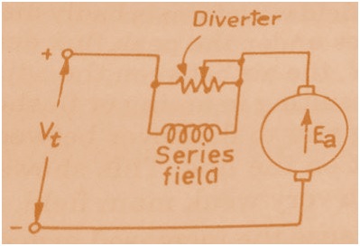
As shown in figure, a variable resistance called diverter is connected in parallel to the field winding of DC Series Motor. As the resistance of Diverter is changed, the field flux is changes which in turn cause the speed of DC Motor to change.
Tapped Field Control:
The connection diagram of tapped filed control is shown in figure below.
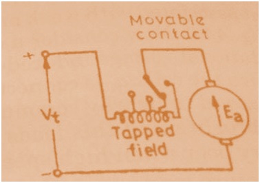
When the field winding is tapped, the number of series field turns N changes as tap is changed from one position to another due to which Megnetomotive Force i.e. mmf = NI, where I is the current flowing through the field winding, changes which cause the filed flux to change. In this way by changing the Tap, field flux is changed which cause speed of DC Motor to change.
Series Parallel Field Control:
In this method, series field winding is divided into two equal halves which then connected in series or parallel. Assume the two equal halves of series filed winding is connected in series as shown in figure below.
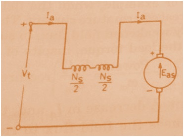
Let the current flowing in the Armature of DC Series Motor = Ia and back / counter emf = Eas
Therefore, filed mmf Fs= Ia(Ns/2 + Ns/2) where Ns = Series Field turns in each half
So, Fs = IaNs …………………………………..(1)
and, Eas = Vt – Ia(Ra+Rs) where Ra = Armature Resistance and Rs = Field Resistance
Now assume the two equal halves of series filed winding is connected in parallel as shown in figure below.
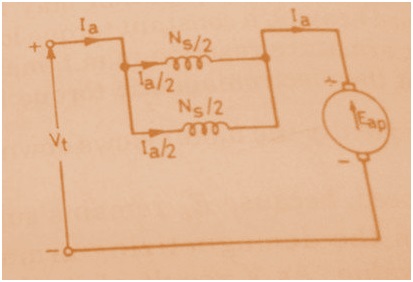
As both the halves are in parallel therefore Ia/2 current will flow in each half of the series field winding of DC Series Motor. Let the field mmf be Fp then
Fp = (Ia/2)(Ns/2)×2 = IaNs/2
Therefore,
Fp = IaNs/4 ……………………………………………(2)
If the resistance of field winding is Rs then resistance of each equal half = Rs/2 and because both halves are connected in parallel therefore equivalent field resistance = Rs/4.
Eap = Back emf
Eap = Vt – Ia(Rs/4+Ra)
Thus we see that, Eap> Eas
Now, as back emf is directly proportional to Ø×Wm,
Eap/Eas= Wm2(IaNs/2)/Wm2(IaNs) ……………[From equation (1) and (2)]
Hence,
|
ωm2 = 2ωm1(Eap/Eas)
|
Thus for parallel connection of series field coils results in higher operating speed of the DC Series Motor.
Please write you views and suggestion. Thank you!