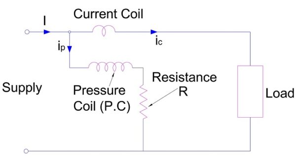
Electrodynamometer Wattmeter consists of two coils, pressure coil (PC) and current coil (CC). Pressure coil is connected across the circuit whose power is to be measured and current coil is connected in series. Thus circuit voltage is impressed across the PC and CC carries the circuit current. For constructional detail please read Electrodynamometer Wattmeter – Construction
Working Principle
Let the rms voltage of circuit is V and current flowing is I. We need to measure the power consumed / delivered of the circuit using electrodynamometer wattmeter. For this we connect the wattmeter to the circuit as shown in figure below.
Instantaneous value of voltage across PC = 2VSinwt
As a high value of series resistance is connected in series with the PC, therefore PC circuit can be assumed purely resistive. Therefore the current flowing through the PC is in phase with the circuit voltage V and given as
ip = Voltage across the PC / Series Resistance
= √2VSinωt / Rp , Rp = Series resistance connected to PC
If the circuit current is assumed lagging by an angle Ø, then the current through the CC is given as
ic = √2ISin(ωt – Ø)
But we know that,
T = i1i2dM/dƟ
In case of electrodynamometer wattmeter, i1 is current through PC and i2 is current through CC. Therefore deflecting torque
T = ipic dM/dƟ
= [√2VSinωt / Rp]x[√2ISin(ωt – Ø)]dM/dƟ
= 2VI SinωtSin(ωt – Ø) dM /dƟ
Since 2SinASinB = Cos (B-A) – Cos (A+B), therefore
T = [VICosØ – VICos(2ωt – Ø)] dM/dƟ
The above expression gives the instantaneous deflecting torque of electrodynamometer wattmeter. But the instrument will respond to the average deflecting torque over a time period. Therefore we need to calculate the average of deflecting torque Td.
Average deflecting torque
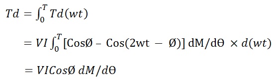
Thus we observe that, the average value of deflecting torque is proportional to the active power (VICosØ) of the circuit.
Controlling torque is provided by spring. Therefore controlling torque Tc is given as
Tc = KƟ
where K = Spring constant and Ɵ = Final steady deflection
At balanced condition,
Controlling Torque Tc = Deflecting torque Td
KƟ = VICosØ dM/dƟ
Ɵ = [VICosØ / K] dM/dƟ
= P dM/dƟ where P = VICosØ / K
Thus we see that, angular deflection of electrodynamometer is proportional to the active power being measured.
Shape of Scale of Electrodynamometer Wattmeter
The shape of scale of this instrument depends on the variation of dM/dƟ i.e. on the variation of mutual inductance between the fixed coil and moving coil. By properly designing the fixed (Current Coil) and moving coil (Pressure coil),dM/dƟ can be made to vary linearly over a range of 40 – 50° on either side of the zero mutual inductance as shown in figure below.
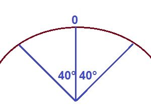
If the position of zero mutual inductance is at the midscale, then the scale will be uniform over a range of 80-100° which covers almost the entire scale range.