This article explains the 120° mode inverter with the help of relevant circuit diagrams, output waveforms. Formulas for phase and line voltage & merits and demerits of 120° Mode inverter over 180° mode inverter has also been explained.
For 120° mode inverter, each thyristor conducts for 120° of a cycle. Like 180° mode, 120° mode inverter also requires six steps, each of 60° duration, for completing one cycle of the output AC voltage. Here it should be noted that step is nothing but the change in firing of one thyristor to the next thyristor in a proper sequence.
Circuit Diagram:
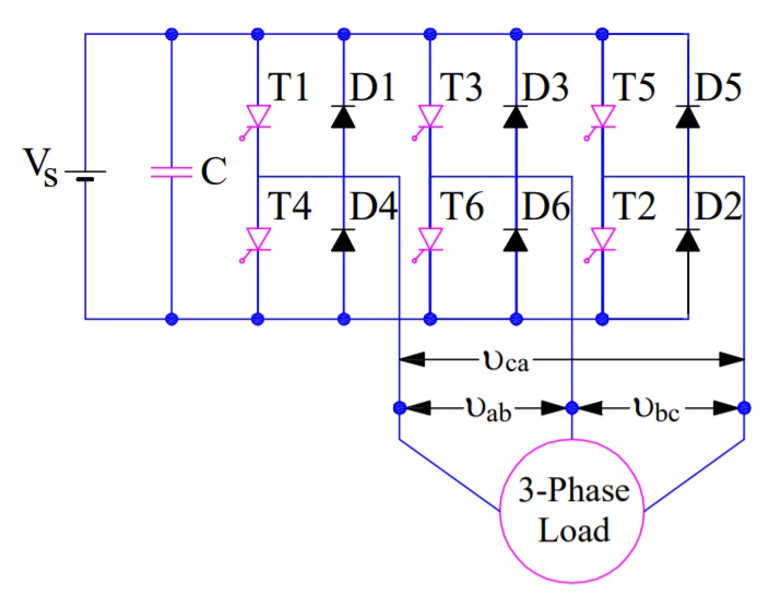
The power circuit diagram of a 120° Mode Inverter is shown in the figure below.
Operation of 120° Mode Inverter:
The firing sequence for 120° Mode Inverter Operation is tabulated below.
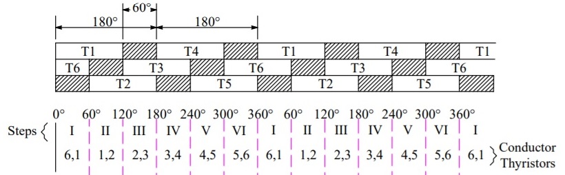
It can be seen from the above table that each of the thyristor conducts for 120° duration only and it remains off for the next 60°. This is different from 180° operation mode where each thyristor conducts for 180° duration.
In the first row of table, T1 is shown to be conducting for 120° and for the next 60° neither T1 not T4 conducts. T4 is turned ON at wt=180° and it further conducts for next 120° i.e. up to ωt = 300°. This simply means that for 60° interval i.e. from ωt=300° to 360°, neither T1 nor T4 conducts. In fact, at ωt = 300°, T4 is tuned OFF and at ωt = 360°, T1 is turned ON again.
In the second row of table, T3 is turned ON at ωt = 120° and it conducts for next 120°. Then 60° interval elapses during which neither T3 nor T6 conducts. At ωt = 300°, T6 is turned ON. It also conducts for next 120° and then 60° interval elapses after which T3 is turned ON again. The thrird row is also completed in the same manner.
The table for firing sequence can be used to define the steps of the three phase inverter for its 120° mode operation. In Step-I, T1 & T6 should be gated; T1 & T2 for step-II; T2 & T3 for step-III and so on. During each step, only two thyristors are conducting- one from the upper arm and another one from the lower arm.
Calculation of Phase and Line Voltages:
To calculate the line & phase voltage at the load terminals for 120° Mode Inverter, we will have to draw equivalent circuit diagram of the three phase inverter for each of step. While drawing equivalent circuit, it is assumed that the load is STAR connected and resistive in nature. Figure below shows the equivalent circuit for Step-I and Step-II.

In step-II, only two thyristors T1 & T6 are conducting. These conducting thyristors are shown as a closed switch and remaining non-conducting thyristors are shown as an open switch in the equivalent circuit diagram.
With reference to the equivalent circuit of Step-I, it may be noted that load terminal “a” is connected to the positive bus while terminal “b” is connected to negative bus. This means the voltage across terminals “ab” will be equal to the source voltage Vs. It is also clear that, load terminal “c” is open in this step. Let us now calculate the phase to neutral voltage and phase to phase voltages in step-I.
Phase to neutral voltage Vao
= Vs/2
Phase to neutral voltage Vbo
= -Vs/2
Phase to neutral voltage Vco
= 0
Line voltage Vab, Vbc and Vca may be calculated using simple arithmetic as shown below.
Vab = Vao + Vob
= Vs
Vbc = Vbo + Voc
= -Vs/2
Vca = Vco + Voa
= -Vs/2
The phase and line voltages for all the remaining steps may also be calculated in the same way using their equivalent circuit. I am not calculating these voltages for the remaining steps. These phase and line voltages may be plotted to get the output voltage waveform.
Output Voltage Waveform of 120° Mode Inverter:
The output voltage waveform of three phase inverter for its 120° mode Inverter is shown below:

Following points should be noted from the output voltage waveform:
- Phase voltage have one positive and one negative pulse in a cycle of output alternating voltage. These positive & negative pulses are of the same duration of 120°.
- The line voltage have six step per cycle of output alternating voltage.
Merits and Demerits of 120° Mode Inverter:
The merits and demerits of 120 degree mode inverter over 180 degree mode inverter are as follows:
- In 180° mode inverter, gate signal is applied and removed simultaneously from thyristors to be fired and commutated respectively. This does not give any time marging for the commutation interval. In fact, there is always a commutation time of a thyristor which is to be turned off. But there is no provision of this commutation time in 180° mode inverter and hence there is always a chance for direct short circuiting of DC source. This difficulty is overcome considerably in 120° mode inverter. In this inverter mode, 60° interval is provided to cater commutation time which is sufficient for safe commutation of conducting thyristor.
- In 120° mode inverter, the potential of only two output terminals connected to DC source are defined at any time of cycle. The potential of third terminal of a particular leg in which neither SCRs are conducting is not well defined. Therefore, the potential of the third terminal is defined by the nature of load. Therefore, the analysis of the performance of 120°mode inverter is bit complicated for a general load circuit. However, for a balanced three phase resistive load, the potential of all the three terminals a, b & c are well defined. This is the reason; the load was assumed to be resistive for the analysis. For a balanced three phase delta connected resistive load, the line voltage as shown in output voltage waveform is obtained directly.
Formula of Phase and Line Voltage:
RMS Value of Phase Voltage
= 0.4082Vs
RMS Value of Line Voltage
= 0.7071Vs
RMS Value of fundamental phase voltage
= 0.3898Vs
RMS value of fundamental line voltage
= 0.6752Vs
Thank you for the light you shed on very interesting subjects