This article outlines the definition and working principle of three phase bridge inverter. 180 degree conduction mode of operation, formula for phase & line voltages of three phase inverter is also explained in this article.
A three phase bridge inverter is a device which converts DC power input into three phase AC output. Like single phase inverter, it draws DC supply from a battery or more commonly from a rectifier.
A basic three phase inverter is a six step bridge inverter. It uses a minimum of 6 thyristors. In inverter terminology, a step is defined as a change in the firing from one thyristor to the next thyristor in a proper sequence. For getting one cycle of 360°, each step is of 60° interval. This means thyristors will be gated at a regular interval of 60° in a proper sequence so that three phase AC output voltage is synthesized at its output.
Circuit Diagram of Three Phase Bridge Inverter:
Figure below shows a simple power circuit diagram of a three phase bridge inverter using six thyristors and diodes.
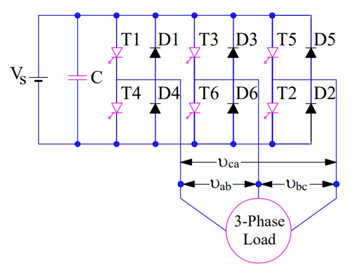
A careful observation of the above circuit diagram reveals that power circuit of a three phase bridge inverter is equivalent to three half bridge inverters arranged side by side. The three phase load connected to the output terminals a, b and c of inverter is assumed to be STAR connected.
In the circuit diagram, the numbering of thyristors is done in the sequence in which they are triggered to obtain voltages vab, vbc & vca at the output terminals a, b & c.
Working Principle of Three Phase Bridge Inverter:
There are two possible patterns of gating the thyristors. In one pattern, each thyristor conducts for 180° and in other, each thyristor conducts for 120°. But in both these patters the gating signals are applied and removed at 60° interval of the output voltage waveform. Therefore, both these models require a six step bridge inverter. Now, we will discuss 180° model of this three phase inverter. 120° mode inverter will be explained in the next article.
180° Conduction Mode of Three Phase Inverter:
In 180° conduction mode of three phase inverter, each thyristor conducts for 180°. Thyristor pair in each arm i.e. (T1, T4), (T3, T6) and (T5, T2) are turned on with a time interval of 180°. It means that T1 remains on for 180° and T4 conducts for the next 180° of a cycle. Thyristors in the upper group i.e. (T1, T3 & T5) conducts at an interval of 120°. It implies that if T1 is fired at wt = 0° then T3 will be fired at 120° and T5 at 240°. Same is also true for lower group thyristors i.e. (T4, T6 & T2).
On the basis of the above mentioned firing scheme, a table has been prepared which shows the conduction period of various thyristors of three phase inverter.

You may notice from the first row of the above table that T1 conducts for 180° while T4 conducts for next 180° and then again T1 for 180° and so on. In the second row, T3 from the upper group is shown conducting 120° after T1 starts conducting. After T3 conducting for 180°, T6 conducts for the next 180° and again T3 for next 180° and so on. Further, in the third row, T5 from the upper group starts conducting 120° after T3 or 240° after T1. After T5 conduction for 180°, T2 conducts for next 180°, T5 for the next 180° and so on. In this way, the pattern for firing of thyristors are identified.
From the above table, the six steps for firing of thyristors may be formulated. As you can see from the table that, the overlapping period of the three SCRs are only 60°, this is the reason, it is said that each step for a three phase bridge inverter is 60°. Let us now try to define the steps.
Step-I: In step-I, thyristors T1, T6 and T5 conducts.
Step-II: T1, T2 and T6 conducts. Mind that T5 is turned off.
Step-III: Now, will have to turn off T6. Therefore, this step will comprise of conduction of thyristors T1, T2 and T3.
Step-IV: This time, T1 has to be turned off and hence, T2, T3 and T4 shall conduct is this step.
Step-V: T4, T3 and T5 conducts and T2 is turned off.
Step-VI: T4, T6 and T5 conducts and T3 is turned off.
From the above steps, you may notice that in each step of 60°, only three SCRs are conducting – one from the upper group and two from the lower group or two from the upper group & one from lower group.
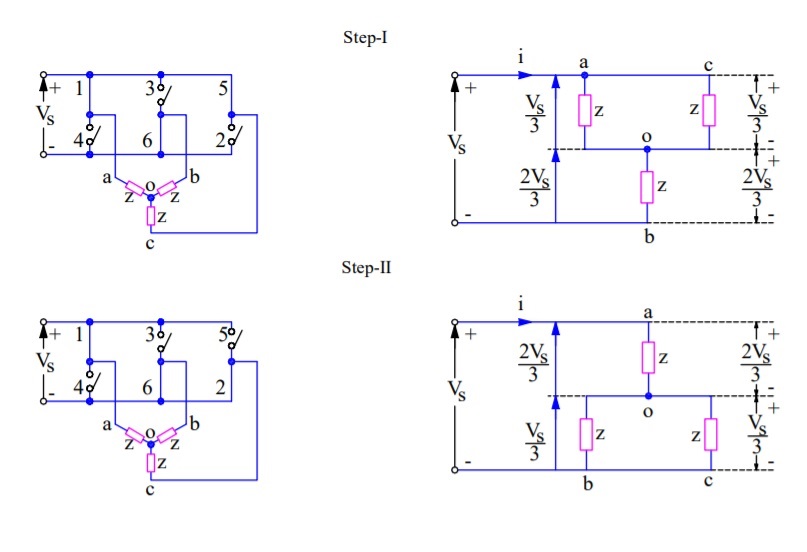
Well, it is time now to draw equivalent circuit diagram for each of the steps. Equivalent circuit for Step-I & II are shown below.
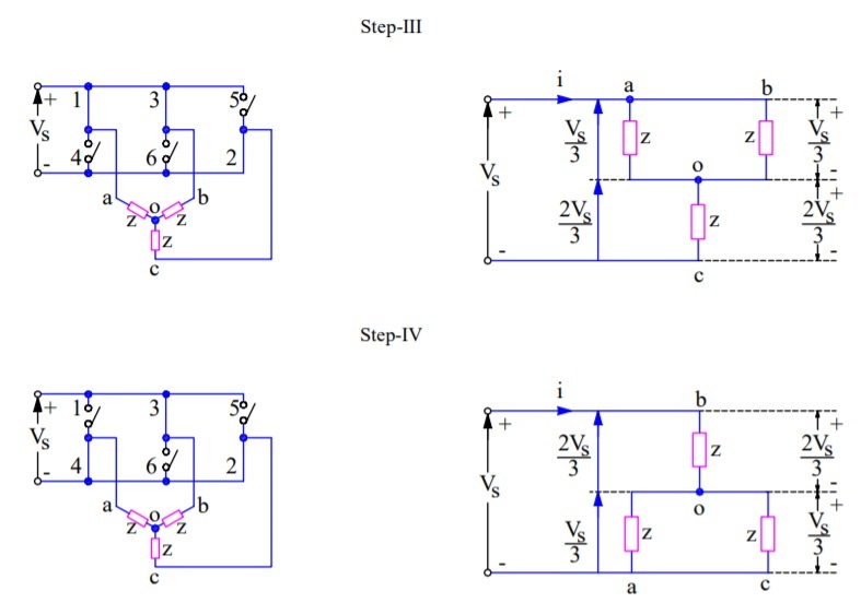
Equivalent circuit for Step-III & IV for three phase bridge inverter is shown below.
During Step-I, SCRs 5, 6 & 1 are conducting. These are shown as closed switches and the non-conducting SCRs are shown as open switches. The load terminals a & c are connected to the positive bus of DC source whereas terminal b is connected to the negative bus of DC source. The load voltage vab = vbc = Vs in magnitude. The magnitude of neutral voltage can be calculated as shown below:

The above line to neutral voltage may be written as Vao = Vco= (Vs/3) and Vbo = -(2Vs/3).
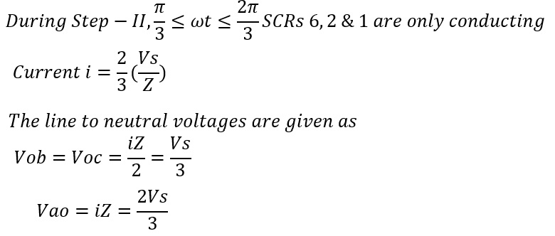
The above line to neutral voltage may be written as Vbo = Voc= -(Vs/3) and Vao = (2Vs/3). The output voltages as calculated for step-I & II are plotted to get the output voltage waveform of the three phase bridge inverter. The variation in phase voltages for remaining steps are calculated in the same manner and plotted. The output voltage waveform is shown below.
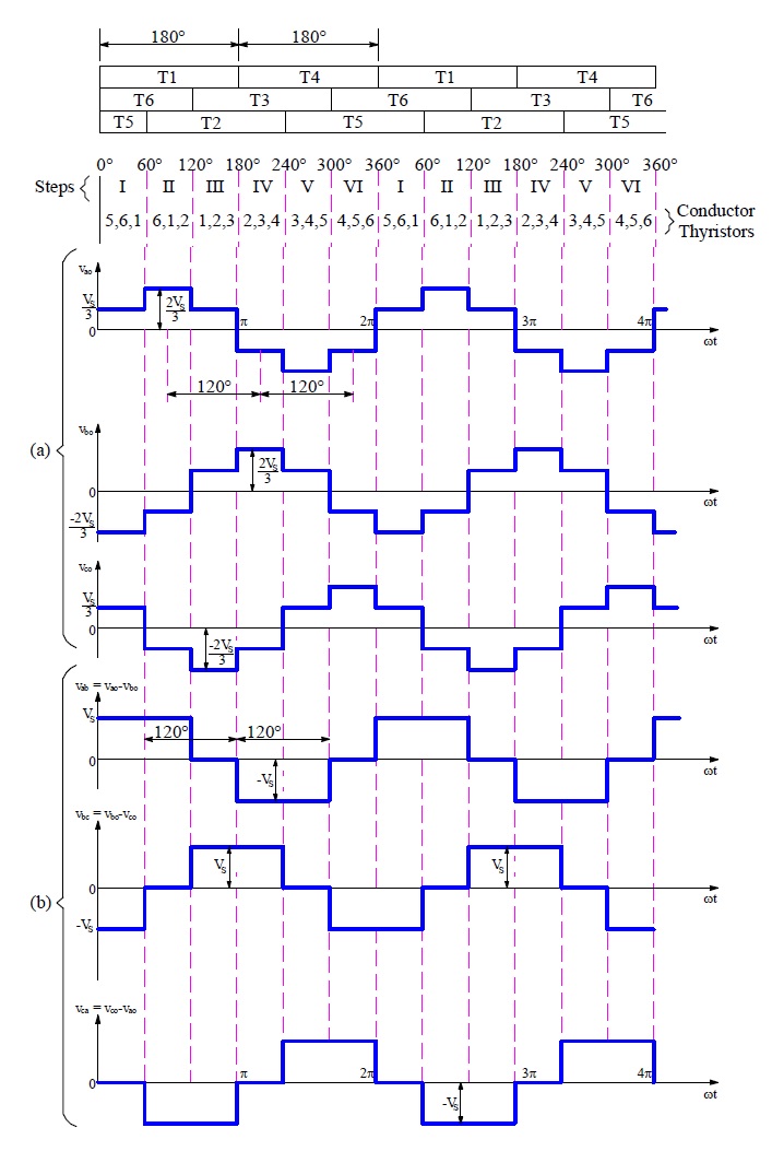
From the above waveform, it is clear that for each cycle of output voltage of each phase, six steps are required and each step has a duration of 60°.
The line voltage Vab = Vao + Vbo or Vab = Vao – Vbo is obtained by reversing Vbo and adding it to Vao. This is shown in the output waveform (b). Similarly, line voltages Vbc & Vca are plotted.
Following points may be noted from the output waveform of three phase bridge inverter:
- Phase voltages have six steps per cycle.
- Line voltages have one positive pulse and one negative pulse each of 120° duration.
- The phase and line voltages are out of phase by 120°.
- The line voltages represent a balanced set of three phase alternating voltages. These voltages are independent of the nature of load which may consists of any combination of resistance, inductance or / and capacitance or load may be balanced or unbalanced, linear or non-linear.
The purpose of diode D1 to D6 is to allow the flow of current through them when the load is inductive in nature.
Formula of Line and Phase Voltage:
RMS value of Line voltage VL is given as below.
VL = 0.8165Vs
RMS Value of phase voltage Vp is given as below:
Vp = 0.4714Vs
RMS value of fundamental line voltage VL1
= 0.7797Vs
RMS value of fundamental phase voltage Vp1
= 0.4502Vs