Definition:
Composite Error of a Current Transformer (CT) is defined as the rms value of difference between the ideal secondary current and the actual secondary current. It includes ratio error, phase error and the effect of harmonics present in the exciting current. Composite error is used to express the accuracy of protection class CT.
You might have seen protection class CT 5P. Here 5P means a Protection class CT whose composite error shall not exceed 5% at its accuracy limit primary current. To be more clearer, consider 5P10 CT. This means that the composite error of CT will not exceed 5% when primary current is 10 times of the rated current.
Before we go into the calculation part, first of all we understand the term ideal secondary current. Ideal secondary current means the CT secondary current when following are assume:
- Leakage flux is negligible. This means all the flux generated by primary is linked with the secondary.
- Core loss i.e. hysteresis and eddy current loss is negligible.
- Saturation curve of core is linear.
Considering the above assumptions, the secondary current will be exact replica of the primary current. This means, the phase and ratio error will be zero. This is called ideal secondary current.
Calculation of Composite Error:
Let us now derive the formula for Composite Error. For this, carefully observe the phasor diagram shown below (symbols have their usual meaning):
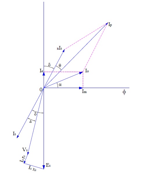
The ideal secondary current here is Is whereas the actual CT secondary current (Ip/n) assuming transformation ratio to be “n”. It may be noted that this difference between the actual and ideal secondary current is due to core loss, magnetizing current component and non-linearity of the saturation curve of core. To find the difference between the two, we should consider the instantaneous value of is and ip and vector subtraction should be used. This difference is equal to the excitation current (I0) of the CT as evident from phasor.
Difference between the ideal secondary current and actual secondary current
= [is – (ip/n)]
= (nis – ip)/n
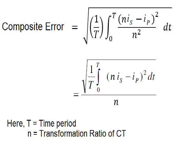
Now, we need to find the rms value of this difference in between the ideal secondary current and actual secondary current.
Percentage Composite Error is defined as the composite error expressed as the percentage of actual CT secondary current. It is often denoted by “ε”. Thus % composite error is calculated as
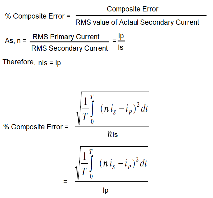
Formula of Composite Error of CT:
The formula of percentage composite error of current transformer is given below.

Thank you for the simple way you use to shed clarity on difficult subjects.
I would be grateful to have clarity on VTs also.
Dear Sir, thank you for the concise explanation for ratio error. Can you also show the derivation of phase error in %Isn/Ip?