Double Bus Single Breaker Scheme is also known as Main cum Transfer Bus Scheme. In this scheme, two bus bars, four Isolators / Disconnect Switch, One Earth Switch and one Circuit Breaker is used in one Bay for switching purpose. What is Bay? You will come to know this terminology latter in this article. This article outlines Double Bus Single Breaker Scheme, Trip Transfer Switch (TTS) and Bus Coupler Breaker and its purpose.
A schematic diagram of Double Bus Single Breaker Scheme is shown in figure below.
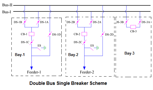
In Double Bus Single Breaker Scheme, two buses Bus-I and Bus-II are used to supply feeders. One bus serves as Main bus whereas other bus serves as main as well as transfer bus. Generally Bus-I acts as Main Bus whereas Bus-II acts as main cum transfer bus. This is the reason, Double Bus Single Breaker Scheme is also known as Main cum Transfer Bus Scheme. But you might be wondering what do I mean by Transfer Bus?
Transfer Bus is one on which any feeders can be connected through transfer isolator i.e. DS-1D / 2D. It must be noted that only one feeder can be transferred to Transfer Bus at any time. In our schematic diagram, Bus-II is transfer bus as DS-1D / 2D connects any feeder to Bus-II. Under normal condition, some feeders are connected to Bus-I and remaining feeders are connected to Bus-II. Thus, both the buses serve the purpose of Main Bus.
Let us now discuss about Double Bus Single Breaker Scheme in detail. As can be seen from the schematic diagram, four isolators i.e. DS-A, DS-B, DS-C are DS-D are used. The Disconnect Switch (DS), often called Isolator, which is connected to Bus-I and Bus-II are called Main Isolator. Thus, DS-1A, DS-1B, DS-2A, DS-2B, DS-3A and DS-3B are main isolators. The DS connected to the load end is called Load Isolator viz. DS-1C and DS-2C. Earth Switch is connected toward load side of Load Isolator. DS-1D and DS-2D are called Transfer Isolators as they directly connect the load to Bus-II. What does this means? This means, any feeder can directly be transferred to Transfer Bus-II through Transfer Isolator. Circuit Breaker of that particular feeder does not come into picture.
In the schematic diagram, each of the feeders with their switching devices is called Bay. Three bays are shown in the schematic diagram. One is Feeder-1 bay, second one is Feeder-2 bay and the third one is Bus Coupler Bay. The purpose of Bus Coupler bay is to connect both the Buses i.e. Bus-I and Bus-II. Under normal condition, bus coupler breaker (CB-3) remains in close condition.
For various conditions, the configuration for DS, Breaker and Earth Switch are:
Case-1: Feeder-1 connected to Bus-I
DS-1A: Close, DS-1B: Open,
DS-1C: Close, DS-1D: Open,
ES: Open and CB-1: Close
Case-2: Feeder-2 connected to Bus-II
DS-2A: Open, DS-2B: Open,
DS-2C: Close, DS-2D: Open,
ES: Open and CB-2: Close
Upon careful observation of the above configuration, you might ask that, what is the function of Transfer Isolator as it remains in open condition irrespective of Feeder is connected to Bus-I or Bus-II. In fact Transfer Isolator viz. DS-1D / DS-2D plays a vital role under some special conditions. Let us understand the function of Transfer Isolator in detail.
Function of Transfer Isolator:
As discussed, the purpose of Transfer Isolator is to directly transfer the feeder from main Bus-I to Bus-II. But when this function is required? Let us assume that Feeder-1 is connected to Main Bus-I and we want to take its Breaker i.e. CB-1 under maintenance. There are two options:
- Take shutdown of Feeder-1. This practically not possible as nobody likes outage.
- Take CB-1 under maintenance without taking the shutdown of Feeder-1.
As Feeder-1 is connected to Bus-I, DS-1A and CB-1 are in close condition. But, as we want to work on CB-1, its isolators DS-1A and DS-1C must be open. This is required to insure positive isolation of breaker from source and load side. As DS is an off load device we cannot open it when the load is connected. Isn’t it? So what to do?
Well, follow the following sequence of operation:
- Transfer all feeders connected to main Bus-II to main Bus-I one by one. (Why?)
- Ensure main Bus-II is charged through bus coupler breaker CB-3 and its isolators DS-3A & 3B are in closed condition.
- Ensure that all the transfer isolators (in our schematic diagram DS-2D) are open.
- Put trip transfer switch (TSS) of CB-1 from NORMAL to INTER position. (What is TTS?)
- Close transfer isolator DS-1D.
- Open DS-1A and DS-1C sequentially. Since DS-1D is close, there is a path for power flow to Feeder-1. Hence, DS-1A and DS-1C can be opened.
- Put trip transfer switch of CB-1 from INTER to TRANSFER position.
Above sequence of operations, transfers Feeder-1 from main Bus-I to Bus-II. But you may have some doubts like why do we need to transfer all the feeders from Bus-II to Bus-I before we can transfer any feeder from Bus-I to Bus-II and what is Trip Transfer Switch (TTS)? Let us address these doubts one by one.
Why do we need to transfer all feeders from Bus-II to Bus-I?
Suppose we do not transfer any feeders from Bus-II to Bus-I prior to transferring Feeder-1 to Bus-II. This means, Feeder-1 is connected to Bus-II directly through DS-1D (without CB-1), Feeder-2 is connected to Bus-II through DS-2B and CB-2 and bus coupler CB-3 is close. Now consider a fault in Feeder-1. This fault will be seen by all the feeders connected to Bus-II. To isolate the fault, all the feeder breaker (CB-2) connected to Bus-II and bus coupler breaker (CB-3) must open. Thus, we can see that all the feeders connected to Bus-II will get trip in case of fault in Feeder-1 if the feeders connected to Bus-II are not transferred to Bus-I prior to transferring Feeder-1 to Bus-II.
What is Trip Transfer Switch and what is its purpose?
It should be noted that, when Feeder-1 is transferred to Bus-II through Transfer Isolator DS-1D, the protection of feeder gets transferred to Bus Coupler Breaker. (How? As we have already transferred all the feeders connected to Bus-II to Main Bus-I, the only feeder connected to Bus-II is Feeder-1 and the bus coupler breaker CB-3 is the link to connect Bus-I & Bus-II). Under the condition of fault in Feeder-1, bus coupler breaker CB-3 trips to isolate the fault from the healthy section of the system. This means, all the protection of Feeder-1 should be transferred to Bus Coupler Breaker CB-3.
Trip Transfer Switch (TTS) serves the purpose to transfer all the protection of a particular feeder to Bus Coupler Breaker. It has three positions viz. Normal, Inter and Transfer. When the TTS switch is at “Normal” position, the protection of feeder lies with its own breaker. But when TTS is put to “Transfer” position, all the feeder protections are transferred to Bus Coupler Breaker. Now, I think, you also understood the purpose of Bus Coupler Breaker in double bus bar arrangement or scheme.
Purpose of Bus Coupler Breaker:
The main purpose of Bus Coupler Breaker in Double Bus Single Breaker Scheme, is to connect Bus-I and Bus-II so that power transfer from the two buses can take place to the connected feeders. In case of fault in any bus bar, bus coupler breaker along with connected feeder breakers trips. Tripping of feeder breakers isolate the feeders from faulty bus while tripping of bus coupler breaker isolates the faulty bus from the healthy bus. Thus the feeders connected to healthy bus remain still available.
Apart from this, bus coupler breaker provides protection to the feeder connected to Bus-II through Transfer Isolator i.e. DS-1D / 2D.
Drawback of Double Bus Single Breaker Scheme:
Since, there is only one bus coupler breaker, only one feeder can be transferred to Bus-II. Therefore, only one breaker can be isolated at a time for maintenance purpose without affecting the connected load. In One and Half Breaker Scheme, any number of breakers can be taken into maintenance without affecting the connected load. But only one breaker from a particular diagonal can only be taken in maintenance in one and half breaker scheme.
In Case-2: Feeder-2 connected to Bus-II
If DS-2A ,DS-2B ,DS-2D are open ,how to feed power supply to Feeder -2?
DS-2A: Open, DS-2B: Open,
DS-2C: Close, DS-2D: Open,
ES: Open and CB-2: Close
The conditions are taken to illustrae the function of transfer isolator.
Explanation is very clear and helpful sir…
great
In TTS, What about “INTER” position?