What is Busbar Protection?
Busbar protection is a protection scheme meant to protect the busbar from electrical fault. Various feeders are connected to a busbar through circuit breaker in any of the bus configuration viz. Double Busbar arrangement or one and half breaker scheme. The main purpose of this busbar is to increase the reliability of power system by maintain the evacuation of power in case of tripping of any feeder due to fault. Let us understand this in detail.
Figure below depicts a single bus to which four feeders are connected. Feeder-1 is generator feeder. This means that the generator power is evacuated by remaining three feeders i.e. Feeder-2,3&4. In case there occurs any fault in any feeder (say in Feeder-2), the respective breaker CB-2 will trip. Under this case, the generator power will be evacuated through busbar by Feeder-3&4. Thus the generator will remain stable. But if it happen so that all the feeders i.e. 2,3&4 trips, the generated power will not be evacuated. In this case, the station will either run on house load or will trip its generator. Thus it is clear from above discussion that, busbar arrangement improves the reliability of system.
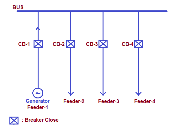
Let us now focus on busbar protection. Suppose there occurs a fault in the bus as shown in figure below.

To protect the bus from faults, it is mandatory to disconnect it from all the power sources as soon as possible. This means that, breaker CB-1, 2, 3 & 4 must open during actuation of busbar protection. You might think that only CB-1 should open. But actually it is not so. Since all the feeders-2, 3 & 4 are connected to Grid, they may feed fault as Grid is an immense source of power. Thus to summarize, all the connected feeders to the bus must open on actuation of busbar protection. The functional requirement of busbar protection is to iolate the busbar in case of bus fault. Busbar protection is thus very important as it leads to disconnection of all connected feeders.
Busbar Protection Scheme or How Busbar Protection Works?
Busbar protection scheme incorporates busbar differential relay (87) which may either be high impedance or low impedance differential relay. When high impedance differential relay is used, it is called High Impedance Busbar protection. Similarly, when low impedance differential relay is used, it is called low impedance busbar protection. Anyhow, differential relay is used to detect the bus fault.
Let us consider one and half breaker scheme to understand busbar protection. In one and half breaker scheme, there are two main buses: Bus-1 and Bus-2. Two feeders are connected to the bus through two main CBs and one tie CB as shown in figure below. In the figure below, CB-1A & CB-1B are main breaker and CB-1C is tie breaker.
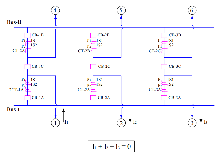
Two feeders 1 and 4 are connected to Bus-1 and Bus-2 respectively. Thus in this breaker arrangement, two different busbar protection are to be implemented to protect Bus-1 and Bus-2. The protection adopted to protect Bus-1 is called the Zone-1 BB protection and that meant for Bus-2 is called Zone-2 busbar protection. The protection scheme for Zone-1 and Zone-2 are identical in all respect. Therefore for better understanding, we will only focus on Zone-1 BB protection.
If you carefully observe the above bus arrangement, you will notice that two CT cores are provided just after CB-1A. Each of the CT secondary cores is connected together in parallel and to the relay in high impedance differential scheme as shown in figure below.
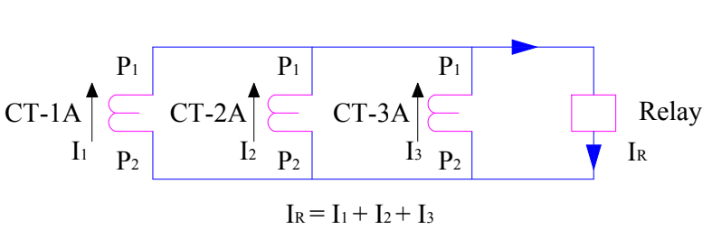
Care must be taken of CT polarity while connecting the secondary in parallel otherwise the relay will operate under normal condition. Let us now consider two cases for better understanding of working of busbar differential protection scheme.
Case-1: A fault in feeder 1.
In this case, the fault current will be fed by all the connected feeders. The flow of current through various feeders is shown by dotted thin blue line in the figure below.

It can easily be seen in the above figure that, (I2+I3) is flowing through the CT-1A but in opposite direction i.e. from 1S2 to 1S1. Therefore the resultant of the currents (I1+I2+I3) will be zero. This can also be obtained from Kirchoff’s current law at the busbar, the sum of current at busbar will be zero. This means,
I1 + I2 + I3 = 0
This means that, no current will flow through the relay and hence busbar differential relay will be stable.
Case-2: A fault in bus-1.
In this case, the flow of current to feed the bus fault is shown by orange color dotted line in figure below.
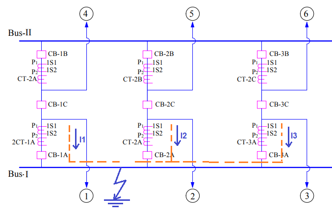
In this case, different amount of current is flowing through CT-1A, CT-2A and CT-3A in the same direction i.e. from 1S1 to 1S2. Therefore their summation (I1+I2+I3) will not be zero as evident from kirchoff’s current law when applied to the point of fault. Therefore a net current equivalent to fault current IF = (I1+I2+I3) will flow through the relay. This will cause busbar differential relay to operate. This in turn will issue trip command to all the connected breaker to the Bus-1 viz. CB-1A, CB-2A and CB-3A.
The main purpose of providing two CT core is make two zones of protection i.e. main zone and check zone. The busbar protection will only operate if both main zone and check zone protection operates. This is so done to eliminate any chance of spurious operation of busbar protection.
Main Zone and Check Zone in Busbar Protection
Since busbar protection leads to complete disconnection of connected feeders, there is no scope for giving a change of spurious actuation of this protection relay. To avoid any spurious actuation, two zones i.e. main zone and check zone scheme are implemented in each of the Zone-1 (for Bus-1) & Zone-2 (for Bus-2) using two different cores of same CT. The wiring and protection scheme is so done that, busbar protection is only actuated when both main zone and check zone relays are operated. This is achieved by DC control scheme of Busbar Protection.
DC Scheme of Busbar Protection
The DC scheme incorporated in busbar differential protection is shown below. The actual scheme may vary but it shows the typical scheme to fulfill the functional requirement of the protection.

Two selection switches CSA and CSCH is provided. The function of CSA is to take main zone busbar protection out of service. When selection switch CSA is operated, the main zone CT cores are shorted and thus bypassed. Similarly, when CSCH is operated, check zone CT cores are shorted and bypassed. Thus the purpose of CSCH is to take check zone out of service.
When CSA and CSCH are in service and main zone busbar protection relay (87-1) and check zone busbar protection relay (87-2) operates, relay 96 gets energized as positive & negative supplies are extended to it. Upon energization of relay 96, its output contacts changes their status from NO (normally Open) to NC (normally Close). These output contacts are wired to breaker trip coils (there are two trip coils in a breaker, TC-1 & TC-2). Thus on energization of 96 relay, breaker gets trip. Since 96 relay is provided for every feeders, all feeder breaker gets trip due to actuation of respective 96 relay. In the above DC scheme, only one 96 relay corresponding to one feeder is shown for simplicity.
Now suppose, we want to take preventive maintenance checks on main zone busbar differential relay (87-1). So what will we do? We will take main zone busbar protection out of service by operating selection switch CSA. Suppose during this period, when main zone relay is out of service a bus fault take place. What will happen? Under this case, on actuation of check zone busbar differential relay (87-2), the relay 96 will be actuated as –ive supply is extended by actuation of 87-2 and +ive supply is already extended through CSA at out position. Thus even though the main zone relay is out, busbar protection will actuate to isolate the bus in case of fault. Similar is the case, when check zone busbar differential relay is taken out of service and bus fault take place.
There is one more relay 50Z in the above DC scheme. This relay is actually the LBB Relay. You might think why LBB relay contact is wired to busbar differential protection scheme. Actually this is required when there is a fault in a feeder and main breaker (like CB-1A) fails to open. This condition is as good as a bus fault as the bus is connected to the feeder fault through stuck close main breaker. Therefore to isolate the fault, it in case main breaker is stuck close it is necessary that the tie breaker (like CB-1C) along with all the connected feeders to the bus should open. This is the reason, LBB protection relay contact of all main breakers are wired to busbar protection DC scheme. It can be seen in the DC scheme that, upon actuation of LBB relay contacts, 96 relay gets actuated to trip all connected breakers to the bus.
Why there is no connection on CSCH side for out position of selector switch as it is there on CSA side?
Reference : DC Scheme of Busbar Protection Dwg.
There is a provision to take out Check Zone also. But it is intentionally not shown in DC Scheme of Busbar protection to keep simplicity for better understanding. You can take main zone as well as check zone out of service.
But without showing that out selector switch how to take check zone out of service?
Actually the provision is there in actual scheme but here in the scheme of Busbar, it was not feasible to show while maintaining simplicity. Did you get it?? What I mean to say is that, there exists such provision in actual scheme. The scheme shown in the post is just a simplified scheme for understanding purpose.
OK. Got it. But not showing that switch will make confusion for the first time reader. Atleast mention that the comment of simplicity in your article for better understanding.
Thank you! Did you find the article helpful?
You are doing great work. Keep going.
Considering double bus-single breaker scheme,suppose fault is between Bus-1 CT and Bus coupler breaker,now this fault actually lies in zone-1 and can be cleared by opening all breaker connected to Bus-1 and bus-coupler, but due to overlapping of zone-1 and zone-2,the fault is also inside zone-2. Can you please explain whether both zone will operate or only zone-1?? If only zone-1 then what is the logic to make zone-2 inopetative in such case??
Identification of faulted Bus is done on the basis of DS closed which is known as CT Switching scheme.
Can you please explain double bus with bus coupler (single CT) concept .
Sure…I will write a post on it. Be there..
Very nice article – Love it 😊
Thank you! Please share.
Thanks and love for such a beautiful explanation and also for clearing the doubts in comment section so nicely.
Can we pace CT between Circuit breaker and Busbar for busbar protection?
If main bus is isolated and power is fed through tie cb, then what protection scheme will be in service? In case of fault in tie bus, what protection will occur?