Generator Compounding Characteristics is a curve depicting the variation of field current required to maintain a constant generator terminal voltage. Generator terminal voltage is maintained constant by controlling its field current either manually or by Automatic Voltage Regulator (AVR).
Let us consider the phasor relation between the excitation voltage Ef and terminal voltage Vt for lagging, unity and leading power factor loads as shown in figure below.
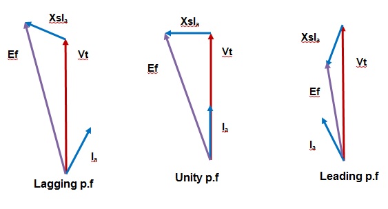
From the above phasor relation, we can have the following poits:
- For lagging load, excitation voltage Ef is leading the terminal voltage Vt. Also, Ef > Vt.
- The excitation voltage Ef is leading the terminal voltage Vt and more in magnitude for unity power factor.
- The magnitude of excitation voltage Ef for leading power factor load is less than the terminal voltage Vt.
Now, let us assume that Generator is running at a lagging power factor of 0.85 and load increase. Therefore Ia will increase. Increase in armature current Ia will lead to increased voltage drop in synchronous reactance Xs i.e. more IaXs. Because of this increase voltage drop, the magnitude of Ef will increase as clear from the above phasor relation. Thus the net effect of increasing load is to increase the Ef which means we need to increase the field current If as Ef is directly proportional to If.
Thus to maintain a constant terminal voltage for a generator operating at lagging power factor, field current should be increased as load i.e. Ia increases.
With the same reasoning we can say that for a generator operating at leading power factor, filed current If should decrease with increase in load i.e. Ia to maintain a constant terminal voltage of generator.
For unity power factor loads, the increase in field current If with increase in Ia is small as compared with lagging loads. The Generator Compounding Characteristics is shown in figure below.
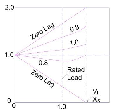
For zero power factor lag, the relationship between terminal voltage Vt and excitation voltage Ef is written as
Ef = Vt + IaXs
Therefore the graph between Ef and Vt is linear as shown in generator compound characteristics. This means field current If should be increased as load increases.
Similarly for zero power factor lead, the relationship between terminal voltage Vt and excitation voltage Ef is written as
Ef = Vt – IaXs
Therefore the graph between Ef and Vt is linear as shown in Generator Compounding Characteristics. This means field current If should be decreased as load increases.
All the above logic derived are incorporated in Automatic Voltage Regulator to maintain constant terminal voltage by changing field current.