We know that, induction motor is quite similar to a transformer; therefore the induction motor equivalent circuit should also be similar to that of a transformer. The only difference between them lies with the fact that, secondary winding i.e. rotor of induction motor rotates to give mechanical output whereas transformer is a static device. Thus the procedure and nature of induction motor equivalent circuit will be the same as that of transformer equivalent circuit.
First of all we will develop circuit model of stator and then rotor individually. Combination of both the circuit models results in equivalent circuit of induction motor.
Equivalent Circuit of Stator:
When 3 phase power supply voltage V1 is extended to the stator winding, a rotating magnetic flux Ø is developed in the air gap. Due to this rotating magnetic flux, a counter emf equal to –E1 is induced in all the 3 phases of stator winding. Now, the supply voltage V1 must balance this counter emf as well as the voltage drop in the stator winding impedance i.e. I1(r1+jx1). Thus we can write
V1 = V1’ + I1(r1+jx1) ………(1)
Where V1’ = –E1, I1 = Stator current
As in case of transformer, the stator current consists of two components. One component I2’ is the load component and counter balances the negative rotor mmf N2’I2. Another component is exacting current Ie. The main purpose of this exciting current is to build the air gap flux and provide necessary no load rotational losses of the induction motor. Mind the difference here. In case of transformer, exciting current (also called no load current) only build the required flux in the core. But in induction motor, apart from building air gap flux, it also provided the no load rotational losses like windage loss and frictional losses.
The exciting current Ie is again having two component, one is core loss component Ic and another is magnetizing current component Im, just like in transformer. The core loss component Ic is in phase with voltage V1’ whereas the magnetizing current Im lags by 90 degree with V1’.
In view of the above discussion, the equivalent circuit model of stator is shown below.
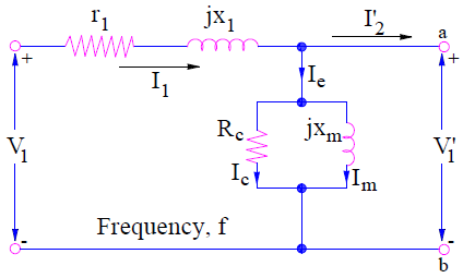
Following points can be observed from the above equivalent circuit of stator of induction motor:
- Ic and Im are connected in parallel. This is because Ic is in phase with V1’ whereas Im lags by 90 degree with V1’.
- Rc is taken just to account for the core loss in induction motor and xm is taken to account for lagging behavior of magnetizing current.
- The above stator equivalent circuit justifies the (1).
Equivalent Circuit of Rotor:
The rotating air gap magnetic flux Ø induces an EMF in the rotor circuit. Due to this induced EMF, a current starts flowing in rotor bar conductors which interacts with the rotating flux to develop a torque. Due to this torque, induction motor starts rotating. Thus it is the induced EMF in rotor, which causes current to flow in the rotor winding. This means, rotor EMF must supply for voltage drop in the rotor winding.
At standstill condition, the induced EMF in rotor = E2 whereas at full load slip s, this EMF becomes sE2. Therefore the voltage equation for rotor at full load slip s will be given as
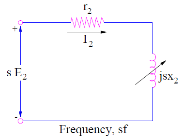
sE2 = I2(r2 + jsx2)
(At slip s, the reactance becomes s times the value of reactance at standstill, this is the reason sx2 is used in above expression)
I2 = sE2 / (r2 + jsx2) ……(2)
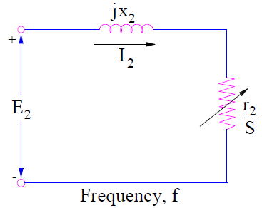
I2 = E2 / (r2/s + jx2) ………(3)
Carefully observe the expression (2) and (3). Both the equation gives the same value and phase of rotor current I2. But still there is one major technical difference between both the equations. What is that?
Equation (2) gives the value of rotor current or load current at a slip s (as rotor EMF is sE2) when the rotor winding resistance and reactance are r2 and sx2 respectively. The equivalent circuit for this is shown below.
But equation (3) gives the rotor current when the induction motor is at standstill condition (as rotor EMF is E2) with rotor winding resistance and reactance r2/s and x2 respectively. Thus equation (2) is correct as it gives the physical interpretation. But equation (3) is useful for getting the overall induction motor equivalent circuit. The rotor equivalent circuit for this condition is shown below.
As we developed the stator and rotor equivalent circuit model, now it’s time to combine them to get the complete induction motor equivalent circuit.
Complete Induction Motor Equivalent Circuit:
To combine stator and rotor equivalent circuit, stator circuit terminal voltage V1’ and E2 must be equal. But unfortunately E2≠V1’. But we can transfer the E2 to primary side i.e. stator side by multiplying it by the turn ratio as in transformer.
Therefore the rotor terminal voltage E2’ when referred to stator side
= E2 (N1’/N2’)
Similarly, the rotor leakage impedance (r2 / s + jx2) and rotor current I2 must also be referred to stator side. These quantities when refereed to stator side will be
(r2 / s + jx2) (N1’/N2’)2 = r2’/s + jx2’ and I2(N2’/N1’) = I2’ respectively.
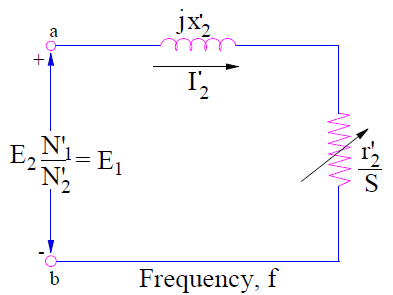
It should be noted that rotor parameters of rotor equivalent circuit corresponding to (3) has been considered for referring to stator side. This is because stator circuit model and circuit model corresponding to (3) are at same line frequency f. The frequency of circuit model for (2), is ‘sf’ and hence it is not considered.
Now ‘ab’ terminal of stator as well as rotor circuit are same. Therefore they can be combined to get the complete induction motor equivalent circuit as shown below.
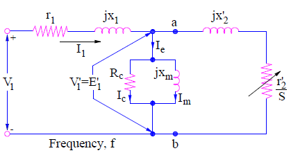
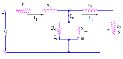
A more generalized induction motor equivalent circuit may be obtained by omitting the prime notation on r2’ and x2’. This is shown below.
Another equivalent circuit may also be obtained by splitting r2/s as
r2/s = r2 + r2[(1-s)/s)]
This equivalent circuit is shown below.
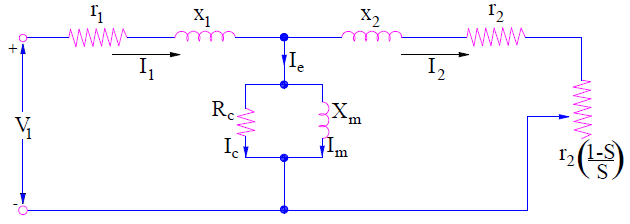
This equivalent circuit shows the resemblances between an induction motor and a transformer. At standstill condition, the value of slip s = 1, therefore r2[(1-s)/s)] = 0. This means the secondary is shorted. This is very similar to that of transformer equivalent circuit when its secondary is shorted. Again, when slip s = 0, r2[(1-s)/s)] = ∞. Thus the equivalent circuit becomes same as that of open circuited transformer. In the above induction motor equivalent circuit, r2 is the actual rotor winding resistance whereas r2[(1-s)/s)] is the electrical analogue of mechanical load.