What is Repulsion Motor?
Repulsion Motor is a special kind of single phase AC motor which works due to the repulsion of similar poles. The stator of this motor is supplied with 1 phase AC supply and rotor circuit is shorted through carbon brush.
Construction of Repulsion Motor:
The main components of repulsion motor are stator, rotor and commutator brush assembly. The stator carries a single phase exciting winding similar to the main winding of single phase induction motor. The rotor has distributed DC winding connected to the commutator at one end just like in DC motor. The carbon brushes are short circuited on themselves.
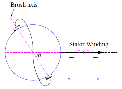
In the above figure, the stator winding have single phase AC winding which produces the working mmf in the air gap. The brushes on rotor are shown to be shorted. As the rotor circuit is shorted, the rotor receives power from stator by transformer action.
Working principle of Repulsion Motor:
The basic principle behind the working of repulsion motor is that “similar poles repel each other.” This means two North poles will repel each other. Similarly, two South poles will repel each other.
When the stator winding of repulsion motor is supplied with single phase AC, it produces a magnetic flux along the direct axis as shown in figure above by arrow mark. This magnetic flux when link with the rotor winding, creates an emf. Due to this emf, a rotor current is produced. This rotor current in turn produces a magnetic flux which is directed along the brush axis due to commutator assembly. Due to the interaction of stator and rotor produced fluxes, an electromagnetic torque is produced. Let us discuss this aspect in detail.
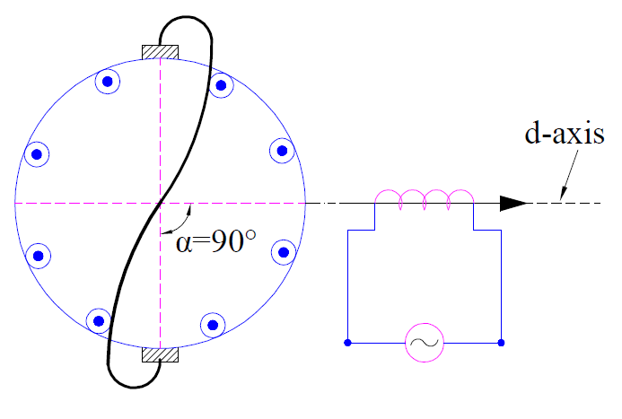
In the above figure, the angle α between the stator produced field and brush axis is 90°. This means, the brush axis is in quadrature with the direct. Under this condition, there will not be any mutual induction between the stator and rotor windings. Therefore, no emf and hence no rotor current is produced. Thus no electromagnetic torque is developed.
This means that motor will not run when α = 90°. As the stator produced flux is unaffected by the zero rotor mmf, this condition is similar to the open circuit transformer. This is the reason, the brush position of α = 90° is called open-circuit, no-load, high impedance or neutral position.
Let us now consider the case when α = 0° as shown in figure below.
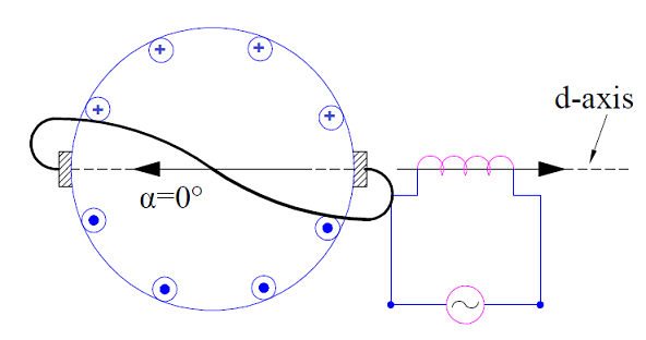
In this condition, a maximum emf is induced across the brushes. This is because, the rotor and stator magnetic flux coincides and hence there is a perfect mutual coupling between them. Since the electromagnetic torque T is given as
Te = k (Stator Field Strength) (Rotor Field Strength) Sinα
where is k is a constant.
No electromagnetic torque is developed as α = 0°. Thus in repulsion motor, no electromagnetic torque is developed when the angle between the stator and rotor magnetic flux axis is either 0 or 90°.
But actually the brush axis occupies a position somewhere in between α = 0° and α = 90° as shown in figure below.
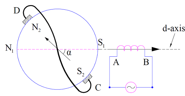
If the stator produced flux is assumed to be directed from A to B, then rotor produced flux must also have a component in a direction opposite to stator produced flux. This is just because of Lenz’s Law. Therefore the rotor flux will be directed from C to D. Notice that it cannot be directed from D to C otherwise it will have a flux component directed toward A to B which is violation of Lenz’s Law.
Since stator flux is toward A to B, South Pole (S1) is generated at A. Similarly South Pole (S2) is generated on rotor at C. Since similar poles repel each other, S1 will repel S2. Due to this repulsion between the like poles, motor will rotate in clockwise direction. This is the reason; this motor is called Repulsion Motor. It is clear from the above figure and discussion that, the direction of rotation of repulsion motor can be reversed by simply changing the brush axis to the other side of filed winding (stator winding).
Torque Equation of Repulsion Motor:
From the above discussion, it is quite clear that for production of electromagnetic torque in repulsion motor, the brush position must not be along the direct axis or quadrature axis. In general, the brush occupies some intermediate position. But for the sake of simplicity, we will assume bush axis vertical and will shift stator field axis at some intermediate position as shown in figure below. This has no effect on the operation and calculation of motor but greatly reduces the calculation effort.

In the above figure, the field axis is making an angle of α with the brush axis. If Is and Ns are the stator filed current and effective number of stator turns then stator mmf IsNs is directed along its axis as shown in above figure. This stator field is now replaced by two fictitious stator coils F and T such that stator mmf IsNs remain unchanged in magnitude as well as direction.
The number of turns Nt of coil T can be found as below.
Mmf of coil T = IsNt
Component of stator mmf along the brush axis = IsNsCosα
IsNt = IsNsCosα
Nt = NsCosα
Similarly, the number of turns of coil F is given as
Nf = NsSinα
Since the magnetic axis of rotor winding and coil T coincides, all the flux produced by coil T will link with the rotor winding. This means that the rotor mmf will be equal to the mmf of coil T as per lenz’s law. Therefore,
Rotor mmf = mmf of coil T
= IsNt
= IsNsCosα
Now, the electromagnetic torque
Te = k (Stator Field Strength) (Rotor Field Strength) Sinα
where is k is a constant.
= k (IsNs)(IsNsCosα)Sinα
= (k/2)(IsNs)2(2CosαSinα)
= (k/2)(IsNs)2Sin2α …. [Sin2α = 2CosαSinα]
Therefore, the torque in repulsion motor is given as
Te = (k/2)(IsNs)2Sin2α
From the torque equation of repulsion motor, it is clear that maximum torque is achieved when stator and rotor magnetic axis are displaced from each other by 45°.
The variation of current and torque with respect to different positions of brush is shown below.
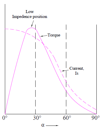
Following points regarding must be noted from the above curve:
- Rotor current is maximum when the brush axis and direct axis coincides.
- Rotor current is zero when the brush occupies a position in quadrature with the direct axis.
- Maximum torque in repulsion motor is achieved when stator and rotor field axis are 45° apart.
Uses:
Repulsion motor is used for loads requiring high starting torque such as hoists, lifts etc.
Does anybody have any information on the Roth Brothers and company? I have a motor manufactured by them sometime between 1895 and 1910. It’s 230 volts ac, 1 hp, 1200 rpm and has an identification number of 10705.
The last graph indicates that the Torque is maximum when alpha < 30 Deg …. but the statement above says the Torque is maximum when alpha = 45 Deg… could you explain that…?