Transformer Equivalent Circuit is the electrical circuit representation of equations describing the behavior of Transformer. In fact equivalent circuit of any electrical device is necessary for its performance analysis and to find any scope of further design modification. The equivalent circuit of a transformer consists of a combination of resistance, inductance, capacitance, voltage etc. This circuits can then be studied and analyzed by applying principles of circuit theory.
Exact Equivalent Circuit of Transformer
Let us now consider the equation which describes the behavior of a Transformer under load condition. To better understand, it is recommended to first read Transformer Phasor Diagram.
E2 = V2 + I2(r2+jx2)
V1 = V1’ + I1(r1 + jx1)
Where E2 = EMF induced in secondary winding
I2 = Load Current
V1 = Primary supply voltage
V1’ = -E1, EMF induced in the primary winding.
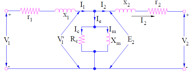
By the above two equations, the transformer equivalent circuit can be drawn as shown below.
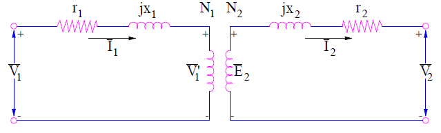
In the above equivalent circuit, (r1 + jx1) and (r2+jx2) are the leakage impedances of primary and secondary windings respectively. The voltage V1’ is treated as the voltage drop in the direction of primary current I1.
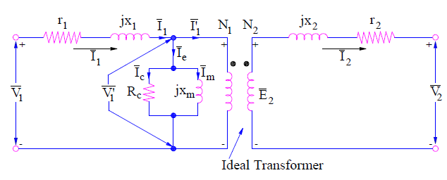
Since the transformer primary current consists of two components: load component current and exciting current. The load component current counteracts the secondary mmf N2I2. Therefore this current is shown to flow in the primary winding in the equivalent circuit shown below. The exciting current Ie consists of core loss current Ic and magnetizing current Im. Since Ic accounts for the core loss of transformer, a resistance Rc is shown in the transformer equivalent circuit such that
Core Loss Pc = RcIc2 = V1’Ic
⇒Rc = V1’ / Ic
Since the magnetizing current Im lags V1’ by 90°, this can be represented in the equivalent circuit by a reactance Xm such that
Xm = V1’ / Im
The resistance Rc and reactance Xm are called core loss resistance and magnetizing reactance respectively. Xm and Rc are shown in the below equivalent circuit. This is the exact transformer equivalent circuit.
Transformer Equivalent Circuit Referred to Primary Side
In transformer analysis, it is better to transfer different parameters to either primary side or secondary side. This is done to make the analysis and calculations easier. Therefore, transformer equivalent circuit should also be obtained when secondary parameters are referred to primary side. Let us obtain this.
Secondary resistance drop when referred to primary side must be multiplied with (N1/N2). Therefore,
Secondary Resistance drop I2r2 referred to Primary
= (I2r2)(N1/N2)
But I2 = I1 (N1/N2)
⇒ Secondary resistance drop I2r2 referred to Primary
= I1 [(N1/N2)2r2] = I1r2’
where r2’ = (N1/N2)2r2
This resistance r2’ is called the secondary resistance referred to primary side. Therefore the total resistance of primary circuit
re1 = r1 + r2’
re1 is called the equivalent resistance of transformer referred to primary side.
Similarly,
The secondary leakage reactance drop when referred to primary side
= (I2x2)(N1/N2)
= I1 [(N1/N2)2x2] = I1x2’
where x2’ = (N1/N2)2x2
This reactance x2’ is called the secondary reactance referred to primary side. Therefore the total resistance of primary circuit
xe1 = x1 + x2’
xe1 is called the equivalent reactance of transformer referred to primary side.
Thus, the total leakage impedance of transformer referred to primary side is given as
ze1 = re1 + jxe1
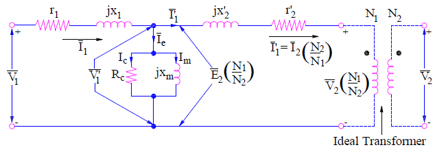
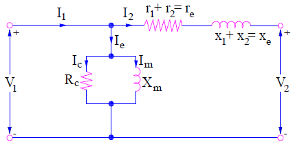
Thus when the secondary resistance drop and reactance drop are referred to primary side, the transformer equivalent circuit will be as shown below.
Transformer Equivalent Circuit Referred to Secondary Side
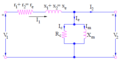
Transformer equivalent circuit referred to secondary side can easily be obtained by transferring primary resistance and reactance drop to the secondary side. This is done exactly in the same way as discussed in arriving at equivalent circuit referred to primary. The equivalent circuit referred to secondary side is shown below.
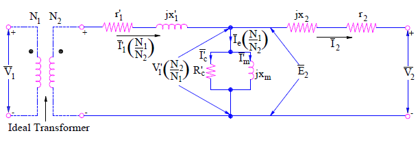
The total leakage impedance of transformer referred to secondary side is given as
ze2 = re2 + jxe2
where re2 = r2 + r1’ and xe2 = x2 + x1’
r1’ = (N2/N1)2r1 and x1’ = (N2/N1)2x1
Generalized Transformer Equivalent Circuit
Generalized transformer equivalent circuit can either be obtained by referring all parameters to primary side or by secondary side and omitting the ideal transformer notation. The generalized form of equivalent circuit of transformer is shown below.
While using the above equivalent circuit, either all parameters should be referred to primary or secondary. One should not mix primary and secondary parameter in the generalized form.
Approximate Transformer Equivalent Circuit
The approximate equivalent circuit of transformer is obtained from the generalized equivalent circuit by moving the shunt branch to either primary side or secondary side. When the shunt branch is moved to primary side, the excitation current Ie don’t flow through the primary leakage impedance. But in actual transformer equivalent circuit, it does flow.
Thus in the above approximate circuit, voltage drop in primary leakage impedance due to exciting current Ie is excluded.
Similarly, when the shunt branch is moved to secondary side, the excitation current does flow through the secondary leakage impedance. But in actual or exact transformer equivalent circuit, it does not flow through the secondary leakage impedance. Thus this approximate circuit includes the voltage drop in secondary leakage impedance due to exciting current Ie.
Since the exciting current Ie is only about 2 to 6 % of the rated winding current, therefore exclusion or inclusion of voltage drop due to this current does not introduce significant error in the calculation. But these simplified equivalent circuits of transformer significantly reduce the computational labor.
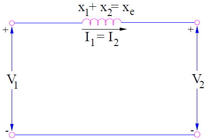
A more simplified equivalent circuit can also be obtained by neglecting the shunt branch. This is justified as the excitation current is quite low as compared to winding current. The simplified circuit is shown below.
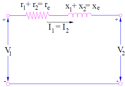
Again, for power transformer the winding resistance is quite low as compared to leakage reactance, therefore it will be quite convenient to neglect primary and secondary resistance. But this is only applicable for large power transformer having name plate rating more than 500 kVA. The circuit is shown below.
The generalized form of transformer equivalent circuit should be used when the exciting current is comparable to the rated current. Again, it should be bear in mind the side where all transformer quantities has been referred while dealing with generalized transformer equivalent circuit.
wow