As we know that principle of induction motor is very similar to the transformer with some differences. An induction motor at standstill condition is similar to a transformer at no load condition. Therefore, the method of drawing the induction motor phasor diagram is also same as that of a transformer phasor diagram. In this post we will discuss the phasor diagram of induction motor at standstill condition and at full load slip.
Induction Motor Phasor Diagram at Standstill Condition:
Before going into the phasor diagram, there are some important points to be taken care:
- Per phase value of induced emf E1 in the stator winding is given as below
E1 = √2πf1kw1N1Ø
where f1 = supply frequency
N1 = Number of series turns per phase
Ø = resultant air gap flux per pole
kw1 = Stator winding factor
- Per phae value of induced emf E2 in rotor winding is given as
E2 = √2πf2kw2N2Ø
where f2 = frequency of induced emf in rotor = sf1
N2 = Number of series turns per phase
Ø = resultant air gap flux per pole
kw2 = Rotor winding factor
- Total air gap mmf Fr of induction motor is the sum of stator mmf (F1) and rotor mmf (F2).
- Magnetizing current Im taken by stator winding from the supply always remains in phase with the resultant flux Ø.
- The induced emf always lags behind the resultant flux Ø by 90°.
Now we are at a stage to draw the induction motor phasor diagram. Let us take the resultant air gap flux Ø as the reference. This flux Ø will be in phase with the resultant mmf Fr. Also, the induced emf E1 and E2 in stator and rotor winding will lag behind the Ø by 90°. This is shown in the below phasor diagram of induction motor.
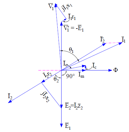
Since the rotor mmf counteracts the stator produced mmf as per lenz’s law, therefore stator takes extra current from supply to counterbalance the effect of rotor current. Therefore under normal condition,
Stator mmf = Rotor mmf
N1’I2’ = N2’I2
where N1’ and N2’ are the effective stator and rotor turns per phase.
This component of stator current is called the load component. In addition to load component, stator also takes magnetizing current Im to build magnetic flux in the air gap. Thus the total stator current I1 = I2’ + Im. This is shown in the above phasor diagram. I2’ is shown opposite to the rotor current I2 for the reason discussed above.
At standstill condition, E2 = I2 (r2 + jx2). The core loss component of stator current Ic is in phase phase with V1’ or –E1. At standstill condition, the friction and windage loss is zero, therefore the stator no load current is given as
I0 = Im + Ic
Since stator applied voltage V1 must balance the stator back emf V1’ or -E1, stator impedance drop I1(r1 + jx1), therefore we can write
V1 = V1’ + I1(r1 + jx1) ……(1)
Similar equation exists for rotor circuit and can be written as
E2 = I2 (r2 + jx2) ……..(2)
The above equations are applied for drawing induction motor phasor diagram as shown in above figure. It can be easily seen from the above phasor diagram that, the power factor (cosɵ) of induction motor at starting is very poor as ɵ is large.
Induction Motor Phasor Diagram at Full Load Slip:
At full load, the slip s of induction is low. The stator voltage equation (1) do not changes when the motor is loaded. But the rotor voltage equation changes with slip. The rotor induced voltage at any slip s becomes sE2 and the rotor circuit reactance becomes sx2. Therefore,
sE2 = I2 (r2 + jsx2)
The above rotor equation when implemented, the induction motor phasor diagram will becomes different from the phasor at standstill condition. The induction motor phasor at full load slip s is shown below.
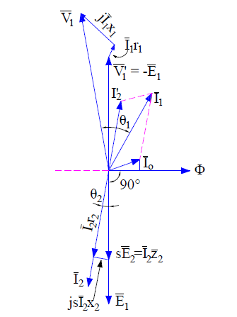
Since at full load condition, some friction and windage loss will exists. This means that stator will have to draw some extra current from the supply main to provide this additional loss. Therefore the total no load current I0 taken by stator is the sum current Ifc and Im. It can be seen from the above phasor diagram that power factor of induction motor improves. generally at full load the power factor ranges in between 0.8 to 0.9.