Low power factor is mainly due to the inductive loads. In industries, mostly inductive loads are used like induction motors, lamps etc.for various purposes. These inductive loads take lagging current and hence results in low power factor. Low power factor has many disadvantages. Therefore, power factor improvement is necessary to get rid of problems associated with low power factor.
Power Factor Improvement Principle
The basic principle for power factor improvement is to connect a device which take leading current in parallel with inductive loads to neutralize the effect of lagging current. Capacitor is one such device. Let us consider this with an example for better understanding of power factor improvement. Figure below shows a single phase inductive load connected to single phase supply voltage V.
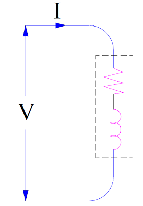
This inductive load is taking lagging current at a power factor of cosØ1. When a capacitor is connected across this load, it will takes current Ic leading by an angle 90 degree with the supply voltage V as shown in figure below.
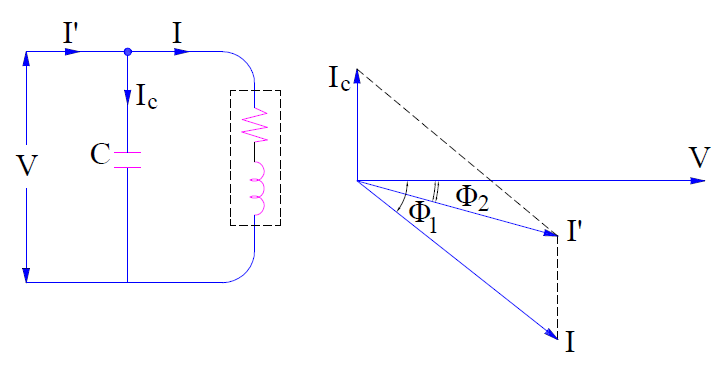
Therefore, the net line current I’ is the phasor sum of load current I and capacitor current Ic. Since the reactive current component (i.e. IsinØ1) of load is partially neutralized by the leading capacitor currentIc, therefore the resultant line current I’ will lag with the supply voltage by an angle less than Ø1. This current I’ is shown to be lagging by an angle Ø2 in the figure. Since Ø2<Ø1, this means that cosØ1<cosØ2. Thus power factor of the load is corrected to cosØ2 from earlier value of cosØ1.
Some Important Points:
1) As reactive current component (i.e. IsinØ1) of load is partially neutralized by the leading capacitor current Ic, the net reactive component of line current will become (IsinØ1 – Ic). But the active current component i.e. IcosØ1 remain constant. Therefore the total line current after power factor improvement is given as
I’ = IcosØ1+ j(IsinØ1– Ic)
Line current prior to power factor correction,
I = IcosØ1 + jIsinØ1
A comparison of above two currents clearly shows that, line current is reduced by power factor improvement.
2) The active current component is not affected by power factor correction. This is expected as only reactive current component is neutralized by power factor correction methods. This is also clear from the phasor diagram. It can be seen that,
IcosØ1 = I’cosØ1
Since active current component remain unaltered, the active power also remain the same as supply voltage is constant.
VIcosØ1 = VI’cosØ1
3) Since the reactive current component is reduced from IsinØ1 to (IsinØ1 – Ic), this means that reactive power demand of equipment is also reduced.
As Reactive Power = Voltage x Reactive Current Component, therefore
Reactive Power demand prior to power factor correction
= VIsinØ1
Reactive Power demand after power factor correction
= V(IsinØ1– Ic)
= VIsinØ1– VIc
= lagging kVAR before p.f improvement – leading kVAR of capacitor
Hence, net reduction in reactive power
= VIc
Power Factor Correction Methods
Power factor correction methods are required to be adopted to improve the low power factor of an equipment and therefore improve the overall p.f of plant or industry.
Power factor correction can be achieved by the use of following equipment:
-
Static Capacitor:
Power factor can be corrected by connecting a static capacitor in parallel with the load taking lagging reactive power. As a capacitor is generator of reactive power, therefore the lagging reactive power demand of the equipment is locally supplied by the static capacitor. Thus the p.f is improved. This method is same as discussed in the Power Factor Improvement Principle. The advantages and disadvantages of this method of power factor correction is discussed below.
Advantage:
- Since capacitor do not consume any active power, this method is quite efficient.
- It require very little to no maintenance.
- Its installation is easy and requires less space.
Disadvantage:
- Switching of capacitor bank requires special breaker or arrangement.
- Their life is short of the order of 10 years.
-
Synchronous Condenser:
A synchronous condenser is an over-excited synchronous motor. When a synchronous motor is over-excited, it takes current leading by an angle of 90° from the supply voltage. This simply means that, it behaves like a capacitor.
Power factor correction is achieved by connection synchronous condenser in parallel with the inductive load whose p.f is to be improved. For detail of how Synchronous condenser improves power factor, please read “How Synchronous Motor Improves the Power Factor?”
Advantage:
- Smooth power factor control can be achieved by varying the filed excitation of synchronous condenser. In case of static capacitor, power factor control is not smooth rather it is in step. This means that switching on capacitor bank will improve power factor by certain amount. If we need to further correct the power factor, we need to add extra capacitor in the bank. But in synchronous condenser, further power factor improvement is achieved merely by changing the field excitation.
- Thermal stability for short circuit current is high for motor winding.
Disadvantage:
- This method is less efficient when compared with static capacitor method due to losses.
- Maintenance cost is high.
- The overall cost of this method is higher as compared to static capacitor method up to 500 kVA.
- An auxiliary equipment is required for the starting of the synchronous condenser. This is because of the fact that, synchronous motors are not self-starting.
-
Phase Advancer:
Phase advancers are used for the power factor correction of induction motors. We know that induction motors operate at lagging power factor. This is because the stator winding of induction motor draws lagging excitation current from the supply main to build air gap flux. If this excitation current can be provided by some other means, then obviously the supply main will be relieved of delivering lagging reactive power to the stator winding. Hence the power factor of induction motor will be improved. This is the basic principle of Phase Advancer.
Phase Advancer is mounted on the motor shaft of induction motor and feeds exciting ampere turns (mmf) to the rotor circuit at slip frequency. The amount of power factor correction depends on the amount of mmf supplied by the phase advancer. It is possible to operate an induction motor at leading power factor by providing mmf more than the required value.
Thanks ever so much I really grab the concept of power factor correction.
Thank you Joshua!