LBB protection is often called CB Failure Protection. As per page Schneider P14x Relay Manual, “Circuit breaker failure protection, monitors the circuit breaker for its opening within a reasonable time in case of fault. If the fault current has not been interrupted following a set time delay from circuit breaker trip initiation, breaker failure protection (CBF) will operate.” In this article, we will discuss the LBB Protection Logic, their effect and definition.
If we check the Logic for LBB protection as given in P14x Relay Manual of Schneider (considering only Three Phase External Trip), refer the LBB logic (taken from Schneider Make P14x relay), following points can be concluded:
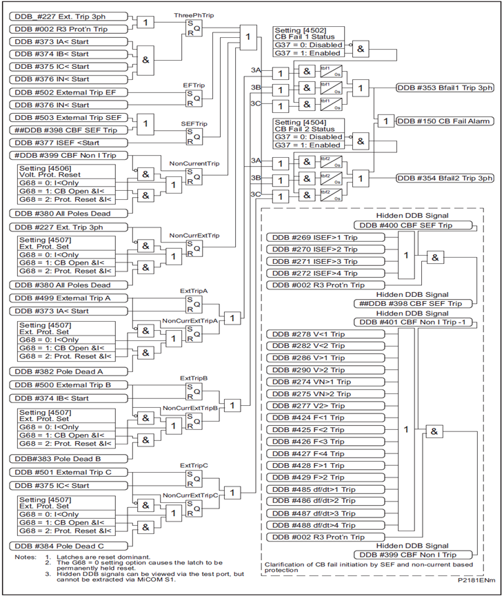
“DDB#227: Ext. Trip 3 ph” gets high i.e. 1 when the opto input to LBB relay corresponding to Lock out Relay (86) / Bus Bar Relay gets actuated. This means if Lock out Relay (86) operates, DDB#227 will have a state of 1.
Let us now consider four different cases:
Case-1: Normal Condition:
Let us consider normal operation of power system where normal load current is flowing and Lock out Relay is under reset condition. Under this normal condition, the input to S-R flip flop will be as follows:
S = 0 (86 Relay Normal)
R = 0 (Normal Load current is flowing)
Q = 0
This means, S-R flipflop will be under reset condition and hence logic output of S-R flipflop Q will be 0. Therefore, the logic output of OR gate 3A will be 0 and hence “DDB#353 Bfail1 Trip 3ph” will be 0. This means LBB will be in reset condition.
Case-2: Fault occurs, Lock-out Relay Actuates and Breaker Fails to Open:
As soon as 86 relay gets actuated by some protection (say distance protection), the input status of S-R flipflop will be as follows:
S = 1
R = 0 (as fault current is more than the setting current)
The logic output of S-R flipflop Q will be 1. Therefore, the logic output of OR gate 3A will be 1 and hence “DDB#353 Bfail1 Trip 3ph” will become high only after a time delay of 200 ms (tbf1 is CB Failt Stage1 timer which is usually set to 200 ms). Once “DDB#353 Bfail1 Trip 3ph” gets high, all mapped output contacts of LBB Relay will become high.
This is successful actuation of LBB protection.
Case-3: Opto input to LBB Relay corresponding to 86 contact gets high a duration less than “CB Fail Stage1” time setiing and normal load current more than I< setting is flowing in the system:
To analyse, first consider the initial state of S-R flipflop to be reset i.e. S=0, R=0 and Q = 0.
For a duration in which 86 output contact gets high, S = 1 and R = 0. Therefore, logic output Q of S-R flipflop will become 1. Consequently the logic output of OR gate 3A will become 1 for the duration less than 200 ms.
Now, 86 output contact gets open before 200 ms (say at 150 ms), the input status of S-R flipflop will be as follows:
S = 0
R = 0
But the earlier state of flipflop is
S = 1
R = 0
Q = 1
Therefore as per the truth table of S-R flipflop, the final state will be
S = 0
R = 0
Q = 1
Thus, the logic output of OR gate 3A will still be high and hence after 200 ms, “DDB#353 Bfail1 Trip 3ph” will become 1 and actaute all mapped output contacts.
From this, it is clear that even though the initiation for LBB has removed before 200 ms, LBB will actuate (load current is more than under current I< setting).
Case-4: Opto input to LBB Relay corresponding to 86 contact gets high and current reaches below I< setting within 200 ms:
To analyse, first consider the initial state of S-R flipflop to be reset i.e. S=0, R=0 and Q = 0.
For the above mentioned case, the status of S-R flip flop will be as follows:
S = 1
R = 1
Therefore, the output of S-R flipflop will be Q = 0 (as initial state is S = 0, R = 0 and Q = 0).
Thus LBB Relay will be in reset condition.
Definition of LBB Protection as per Schneider Relay P14x Manual:
From the above case-2 and case-3, LBB protection is initiated by 86 realy output contact and resets only if the current reaches below set I< value.
To further study the LBB Protection scheme, RAICA Relay Manual was referred. As per RAICA Relay Manual, the Auxiliary 220 V DC supply to relay is extended is the output contact of Lock-out Relay (86) is close. This DC supply is then extended to a timer which in turn initiates trip command after a pre-set time delay if the current though the feeder is more than the setting.
In case, 86 relay gets reset prior to the pre-set time (200 ms), the output contact of 86 relay will open and hence the DC supply to relay will cut off. Thus relay will reset.
Definition of LBB as per RAICA Relay Manual:
LBB Relay issues trip command if the 86 relay output contact is high for 200 ms and current through the feeder is more than 200 ms.
Conclusion:
Lock-out Relay (86) is defined as a relay which once actuated remain in actuated condition untill and unless it is manually resseted. This means, opto input to LBB Relay (P141) corresponding to three phase trip should remain high until 86 relay is manually resetted. In view of this, P141 relay should have intelligence to distinguish in between spuriously high of its opto input bit (for a time less than 200 ms) and actual actuation of 86 relay (which will be high for infinite time).
This concept of Lock-out relay is being defeated in the LBB logic of P14x Relay. Refer LBB Logic. There have been many events were the opto input of LBB Relay gets high for, say 100 ms, due to some human error and LBB relay gets actuated. In such case, the relay should have intelligence to detect that the phenomena is due to human error.
Thus there are two definitions of LBB protection. All the readers are requested to comment / critics for the two definitions.
References:
- Relay Manual of Schneider P14x
- RAICA Relay Manual