Resistive Reach of Distance Relay Characteristics is defined by the fault resistance for which the distance relay characteristics is defined. In MHO type distance relay the major drawback is that resistive reach is defined by the impedance reach and line angle and hence it is not independently settable in the relay. However, it is independently settable in modern Numerical Relay having Quadrilateral Characteristics. In this article, we will discuss the method for calculation of resistive reach setting.
Two types of Resistive Reach are settable in quadrilateral characteristics of distance relay:
- Ph-Ph (Phase to Phase) Resistive Reach, and
- Ph-G (Phase to Ground) Resistive Reach
Calculation for Ph-Ph Resistive Reach:
Ph-Ph resistive reach i.e. Rph is defined by the maximum amount of fault resistance in addition to line impedance for which distance zone will trip regardless of location fault. The definition itself means that phase-phase resistive reach must be defined Zone-1 (R1ph), Zone-2 (R2ph), Zone-3 (R3ph-R4ph) and Zone-4 (R3ph-R4ph). It may be noted that, Zone-3 and Zone-4 share the same resistive reach (R3ph-R4ph).
As phase to phase resistive reach has to cover the maximum fault resistance, therefore, Rph must be set greater than the maximum fault resistance for a phase to phase fault. Generally, Rph is set greater than the maximum fault arc resistance for a phase to phase fault. The arc resistance is given by the following formula:
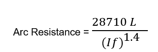
Where, If = Minimum fault current during phase to phase fault in Ampere
L = Maximum spacing between the conductors in meter
Thus, the phase to phase resistive reach must be set greater than the above calculated arc resistance.
Therefore, Rph ≥ Arc Resistance
Apart from the above, we should also consider the load encroachment. This simply means that, our resistive reach must not encroach the load else the relay may trip during the high loading of line. Let us discuss this aspect for calculating the resistive reach.
Consideration of Load Encroachment:
Figure below demonstrates the quadrilateral characteristics of a distance relay and load point Z (Z is the minimum load impedance).
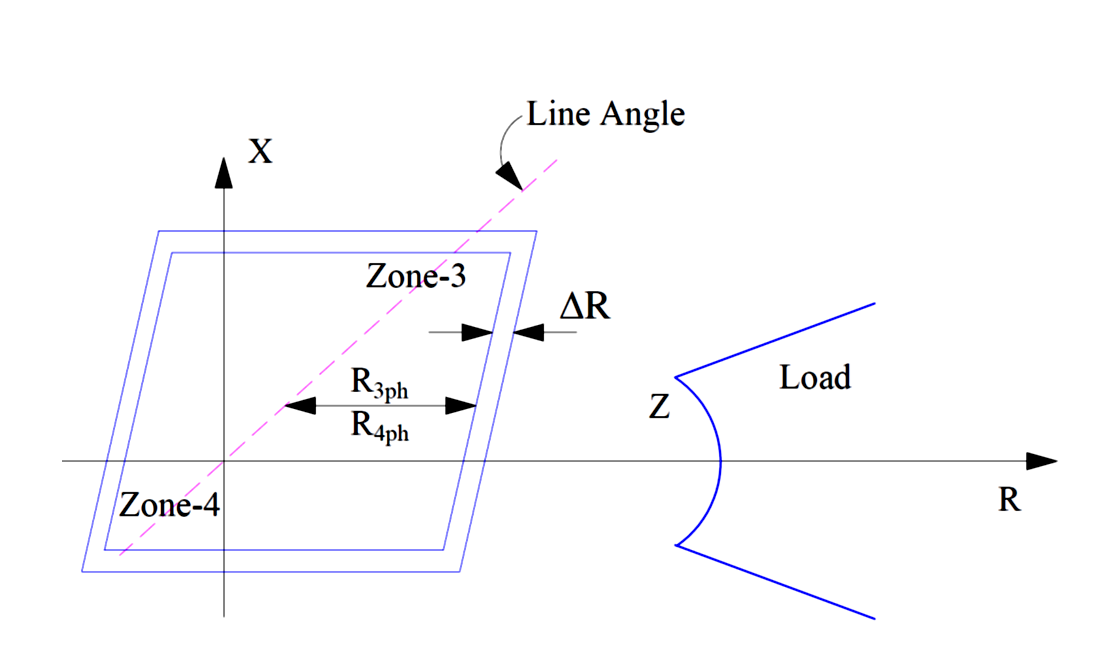
It can also be observed from the characteristics that Zone-3 resistive reach must be set carefully so that it do not encroach the load impedance locus. This is important from system reliability and to avoid spurious tripping of line during heavy loading of line.
Generally, the resistive reach of zone-3 is set less than 80% of minimum load impedance. For power swing consideration, a margin of DR is given. Therefore, it is essential that load should not encroach this DR. In view of this, R3ph – R4ph is set 60% of minimum load impedance. R2ph and R1ph is set 80% of R3ph-R4ph respectively.
Calculation of Minimum Load Impedance:
Now, we must calculate the minimum load impedance. To calculate, we refer Ramkrishna Committee recommendations. As per Ramkrishna Committee recommendation, in the absence of credible data regarding minimum voltage and maximum load expected for a line during emergency system condition, following criteria may be considered for deciding load point encroachment:
- Maximum load current (Imax) may be considered as 1.5 times the thermal rating of the line or 1.5 times the associated bay equipment current rating (the minimum of the bay equipment individual rating) whichever is lower.
- Minimum voltage (Vmin) to be considered as 0.85pu (85%).
Let us now try to calculate the resistive reach setting of a 400 kV line. The Line CT ratio is assumed 1000/1 A and CVT ratio is assumed 400 kV/110 V. Let now first calculate the minimum load impedance.
With reference to recommendation of Ramkrishna committee recommendation,
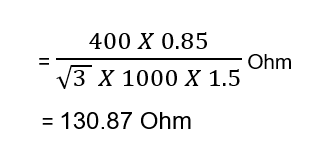
Assumed Line Voltage = 0.85 pu
Assumed Line Current = 1.5 pu
Therefore, minimum load impedance for a 400 kV Line,
It should be noted that, the above calculate for minimum load impedance is in terms of primary. To convert it into secondary we must multiply this by CT/PT ratio.
CT/PT Ratio = (1000×110) / (400×1000)
= 0.275
Minimum Load impedance in terms of secondary
= 130.87×0.275
= 36 Ohms
Let us consider an extra margin of 20% in of minimum load impedance for setting resistive reach of Zone-3.
Therefore, the minimum load impedance in terms of secondary
= 36×0.8
= 28.8 Ohms
Considering power swing and load encroachment, the resistive reach setting for Zone-3 should be 60%.
R3PP = 60% of 28.8
= 17.27 Ohm
As Zone-2 phase to phase resistive reach is 80% of R3PP, therefore
R2PP = 80% of R3PP
= 13.81 Ω
Similarly, Zone-1 phase to phase resistive reach is 80% of R2PP, therefore
R1PP = 80% of R2PP
= 11.05 Ω
Calculation for Phase to Ground Resistive Reach:
The phase to ground resistive reach is defined by the maximum phase to ground fault arc resistance and tower footing resistance for which relay should operate. Again, it should not be encroached by load. Generally, this reach is set 80% of minimum load impedance.
R1PG-G = R2PG-G = R3PG-G
= 80% of 28.8
= 23.032 Ω
Hope you enjoyed the post. Kindly comment for suggestion and value addition. Your feedback will make the article more helpful.
References:
- Schneider Relay Manual (P44X)
- Ramkrishna Committee Recommendation
Thanks for very useful info.
R1PG-G = R2PG-G = R3PG-G. Is this valid?