Single Phase Half Wave Controlled Rectifier, as the name suggests, is a rectifier circuit which converts AC input into DC output only for positive half cycle of the AC input supply. The word “controlled” means that, we can change the starting point of load current by controlling the firing angle of SCR. These words might seem a lot technical. But firing of SCR simply means, the SCR turn ON at certain point of time when it is forward biased.
Single Phase Half Wave Controlled Rectifier Circuit:
A Single Phase Half Wave Controlled Rectifier circuit consists of SCR / thyristor, an AC voltage source and load. The load may be purely resistive, Inductive or a combination of resistance and inductance. For simplicity, we will consider a resistive load. A simple circuit diagram of Single Phase Half Wave Controlled Rectifier is shown in figure below.
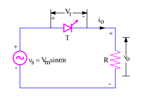
v0 = Load output voltage
i0 = Load current
VT = Voltage across the thyristor T
Following points must be kept in mind while discussing controlled rectifier:
- The necessary condition for turn ON of SCR is that, it should be forward biased and gate signal must be applied. In other words, an SCR will only get turned ON when it is forward biased and fired or gated.
- SCR will only turn off when current through it reaches below holding current and reverse voltage is applied for a time period more than the SCR turn off time.
Well, let us go ahead with the above points in mind. Let us assume that thyristor T is fired at a firing angle of α. This means when wt = α, gate signal will be applied and SCR will start conducting. Refer the figure below.
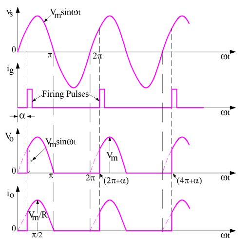
Thyristor T is forward biased for the positive half cycle of supply voltage. The load output voltage is zero till SCR is fired. Once SCR is fired at an angle of α, SCR starts conducting. But as soon as the supply voltage becomes zero at ωt = π, the load current will become zero and after ωt = π, SCR is reversed biased. Thus thyristor T will turn off at ωt = π and will remain in OFF condition till it is fired again at ωt = (2π+α).
Therefore, the load output voltage and current for one complete cycle of input supply voltage may be written as
v0 = VmSinωt for α≤ωt≤ π
i0 = VmSinωt / R for for α≤ωt≤ π
Calculation of Average Load Output Voltage:
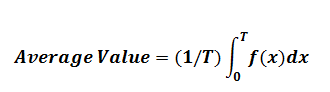
As we know that, average value of any function f(x) cab be calculated using the formula
Let us now calculate the average value of output voltage for Single Phase Half Wave Controlled Rectifier.
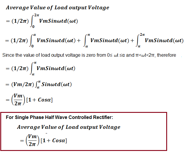
From the expression of average output voltage, it can be seen that, by changing firing angle α, we can change the average output voltage. The average output voltage is maximum when firing angle is zero and it is minimum when firing angle α = π. This is the reason, it is called phase controlled rectifier.
Average load current for Single Phase Half Wave Controlled Rectifier can easily be calculated by dividing the average load output voltage by load resistance R.
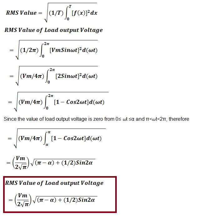
Let us now calculate the root mean square (rms) value of load voltage.
RMS value of load current can be calculated by dividing the rms load voltage by resistance R. This means,
RMS Load Current I0rms= RMS Load Voltage / R
Input volt ampere can be calculated as
Input Volt Ampere
= RMS Supply Voltage x RMS Load Current
= VsxI0rms
very informative guide on 1-phase HW controlled rectifier. Great work.
Thank you!
The equation of single phase half-wave controlled rectifier with Inductive load with freewheeling diode.
really very much informative and simply the best……
Which of the following is used in single phase half wave controlled rectifier
A diode
B Scr
C transistor
D none of these
Thank you so much
आपने बहुत ही अच्छा समझाया है